Hi all,
I am very new to this forum as well as DIY electronic circuits.
I am not an electrical engineering student nor I have sufficient background (I guess ).
).
I have a few questions regarding the building of an audio mixer.
Basically, I am interested to make an audio mixer to combine two audio sources which is from my laptop and my phone into one input to my multimedia speakers.
After hours of Googling around, I found various different schematics which I admit I find it hard to figure out what the components do.
So, it would be good if someone experience enough could explain them to me.
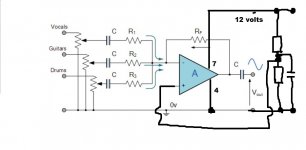
For instance, this schematic below:
(Op-amp Summing Amplifier (Voltage Adder))
May I know what are the uses of the capacitors?
May I assume the capacitors before the amplifier have similar functions and their functions are different from the one after the amplifier?
I do understand that values of R1, R2, R3 and Rf influences the gain of the circuit.
Besides that, the output of the circuit is inverted does it matter if the output is not inverted back?
Furthermore, if I am interested in only unity gain (say R1=R2=R3=Rf), do I still require the amplifier for the mixer to work?
Lastly, are there any websites/readings regarding audio sources and signals. I believe with more understandings regarding audio signals I will be able to understand and design circuits more easily.
Thank you (for going through such long post of mine)!
I am very new to this forum as well as DIY electronic circuits.
I am not an electrical engineering student nor I have sufficient background (I guess
).I have a few questions regarding the building of an audio mixer.
Basically, I am interested to make an audio mixer to combine two audio sources which is from my laptop and my phone into one input to my multimedia speakers.
After hours of Googling around, I found various different schematics which I admit I find it hard to figure out what the components do.
So, it would be good if someone experience enough could explain them to me.
For instance, this schematic below:
An externally hosted image should be here but it was not working when we last tested it.
(Op-amp Summing Amplifier (Voltage Adder))
May I know what are the uses of the capacitors?
May I assume the capacitors before the amplifier have similar functions and their functions are different from the one after the amplifier?
I do understand that values of R1, R2, R3 and Rf influences the gain of the circuit.
Besides that, the output of the circuit is inverted does it matter if the output is not inverted back?
Furthermore, if I am interested in only unity gain (say R1=R2=R3=Rf), do I still require the amplifier for the mixer to work?
Lastly, are there any websites/readings regarding audio sources and signals. I believe with more understandings regarding audio signals I will be able to understand and design circuits more easily.
Thank you (for going through such long post of mine
)!The capacitors stop any DC voltages that might be present. It's normal for all audio amplifiers not to amplify DC signals... it's something we don't want.
So the ones after the pots prevent DC from any source components entering the amplifier/mixer. They also serve another important function. Any DC that is present on a variable resistor can make the operation of the control noisy as it is turned if that current passes through the wiper of the control
The cap after the opamp stops any slight DC voltage (what we call an offset) from being applied to the next stage that the amplifier couples to.
The opamp is a "virtual earth" amplifier. This means that the point at which the signals are "summed" (the - input) always appears to be a zero point with no signal present.
You need to read and understand how an inverting opamp circuit works to really understand how the mixer works.
The mixer (by virtue of bringing the summing point to zero) ensure that there is no interaction between the inputs. If you omitted the opamp then the mixing would be at the mercy of the individual source components properties such as their output impedance.
That the circuit inverts is not a disadvantage although there is thought that absolute phase is important. Try it yourself. If you swap the speaker polarity of both speakers in a stereo setup you have inverted the phase exactly the same as this circuit does. Can you hear any difference ?
Hi, I sincerely appreciate your swift reply!
It did help me clear most of the doubts especially regarding the caps.
Yup, I have studied op-amp circuits (basics) in school and university.
Therefore, I understand how the basic op-amp circuit work (those without capacitors and such).
So, are there any recommended amps to be used in my case here?
How do different amps affect the circuit here?
In addition, are there any recommended capacitance for the capacitors as well as the resistance for the resistors?
Similarly, how do these affect the circuit?
As far as I know, if I use the same resistors across R1, R2, R3 and Rf I will get a unity gain circuit. So, can I use any resistors (like 1k ohm)?
Thanks again!
Opamps first. You need to begin with something that you know will work without running into stability issues.
For learning the ancient 741 takes some beating and will still turn in a "half decent" audio performance. Also consider the TL071 or TL081 FET opamps. All three are compatable and can be swapped and changed as wished.
You do realise that the circuit as drawn runs a "split" supply consisting of a positive and negative rail. For example two 9 volt batteries with a centre tap that becomes "ground".
The value of the caps affect the low frequency response. If they are to small in value then the bass frequecncies are attenuated. Each cap after the pot works in conjunction with the following resistor to form a "first order" high pass filter.
calculators for electronic circuit design
Although the resistors can theoretically be any value in practice the lower limit is determined by the minimum load the opamp can drive. So I would keep Rf at say 10K and scale the other to what you need. Go too high such as 1Meg for Rf and problems such as DC offset (for the 741 type opamp) and problems with noise and poor high frequency response appear. With high values, stray capacitance becomes a factor. So stick to around 10K give or take.
hey guys im new with this forum. i need a circuit diagram for my konzert k10 amp. some of its components value were erased due to hard blow on short circuits. tnx in advance
I would suggest you start a new thread in the appropriate forum
Opamps first. You need to begin with something that you know will work without running into stability issues.
For learning the ancient 741 takes some beating and will still turn in a "half decent" audio performance. Also consider the TL071 or TL081 FET opamps. All three are compatable and can be swapped and changed as wished.
You do realise that the circuit as drawn runs a "split" supply consisting of a positive and negative rail. For example two 9 volt batteries with a centre tap that becomes "ground".
The value of the caps affect the low frequency response. If they are to small in value then the bass frequecncies are attenuated. Each cap after the pot works in conjunction with the following resistor to form a "first order" high pass filter.
calculators for electronic circuit design
Although the resistors can theoretically be any value in practice the lower limit is determined by the minimum load the opamp can drive. So I would keep Rf at say 10K and scale the other to what you need. Go too high such as 1Meg for Rf and problems such as DC offset (for the 741 type opamp) and problems with noise and poor high frequency response appear. With high values, stray capacitance becomes a factor. So stick to around 10K give or take.
Do you mind explaining more on the "split" supply part?
Do you mean the potentiometer there?
For the low frequency response, is it safe to say that:
1. First, I have to find out what resistance am I going to use (say around 10k)
2. Then, I use the calculator to calculate the lowest frequency which the circuit is needed to handle? Say 40Hz which is the lowest my speakers will respond to.
Last edited:
The split power refers to the opamp power supply. For that circuit to work (and it is the normal and correct method), it needs the opamp (assuming the device numbers mentioned) to have a positive supply on pin 7 with respect to "ground" (thats your zero volt line) and a minus supply on pin 4 with respect to ground.
To power the circuit from a single rail, for example from one battery, would require additional components to derive a "mid point" reference level.
Its a subtle thing to grasp. On a single supply the opamp output would have to be biased to half the supply voltage in oder that the output could go "equally high" and "equally low". ON a single 9 volt battery that means the opamp output would be arranged to sit midway at 4.5 volts and then it could go toward 9 volts or down toward zero volts.
The split supply is a recognised and standard way of powering opamps but for battery use single rail operation can be more convenient.
If your speakers go to 40 Hz then you need the reponse to go lower than that by some margin in order that the 40Hz level is un-attenuated. A typical figure would be around 5 Hz.
If you look at op amp datasheets (like on datasheetcatalog.com) you will find they have a drawing that shows how close you can get the input to the supply voltage before they stop working. Plotted against the supply voltage, usually. This means the ground symbol in your drawing post one, is 1/2 way in between the voltages you put on pins 4 (-v) and 8 (+v) of your DIP package op amp.
So the split supply doesn't use a lot of current in the middle, the ground place. Rather than monkey with replacing 9v batteries all the time (at $8 the pair, starting last week), I found a way with two 5 Watt 8v zener diodes and a couple of resistors to turn a DC wall transformer (18 VDC) into a split supply. With only one op amp you could probably get away with cheaper 3 W zener diodes. Schematic is in the last post of http://www.diyaudio.com/forums/anal...improving-disco-mixer-mid-fi-performance.html If you have a 24v wall supply from the charity resale shop, you can use 11v zeners, With a 32 V printer/fax/copier wall transformer you can use +-15 v zeners. The maximum input signal you can mix is roughly +V - (-V) - 4, so my +-8v mixer handles a 9 Vac radio output just fine.
Copying other people schematics is the easiest way to "calculate" the input and output capacitors. I've used .22 uf on the input with 10kohm input impedance, but .1 is cheaper if you have to buy them. 10 uf on the output is usual.
741 sounds vile, TL071 sound nice but latches up (stops working) if you get the input too close to the supply voltage even once. Note the power supply decoupling capacitors (+ to - to ground) are not on your schematic but are necessary for anything faster (slew rate) than a 741 or 4558. 4558 has mediocre sound, NE5532 is better with no latchup and no capacitor required around the feedback resistor. But 5532 comes in the wrong package a lot, have to carefully check you're getting 8 pin dip package.
If you're going to build something, 8 pin DIP package is nice, watch what package you order. In the US mcmelectronics has some nice cheap ($2) dip project boards, there is something similar in France but I lost the link when I had to reload the operating system. Vector board is $10 a slice.
A steel box is useful to keep hum from the transformer away from the op amp, and chokes on the power coming in keep lamp dimmer/switcher power supply/CB radio trash coming in the power lines. A 100 pf cap to ground on each input keeps radio trash from coming in that way.
Have fun.
Last edited:
Hi indianajo,
Comparing opamps and seeing which is "best" is a hot topic generally.
The 741 is fine for experimenting and learning... its cheap, its tough, its stable and it has a low power consumption.
Everything has to be put in perspective. A 741 compared to say a current £$10 "audio" opamp is a bit like comparing a £$1000 CD player to a £$10 portable CD player from the supermarket. There are differences for sure, but the cheapo one can be surprisingly good when slotted into a top flight system. Remember 741's were the industry standard for many years and were used in many hifi products/projects of the day.
If you fit a socket to any projects then you can try different opamps to see if you can hear the differences.
(I'm not trying to make a case for the 741 just that it is absolutely ideal as a starting point for learning and ultimately you might be surprised how "good" it still is when used correctly)
Comparing opamps and seeing which is "best" is a hot topic generally.
The 741 is fine for experimenting and learning... its cheap, its tough, its stable and it has a low power consumption.
Everything has to be put in perspective. A 741 compared to say a current £$10 "audio" opamp is a bit like comparing a £$1000 CD player to a £$10 portable CD player from the supermarket. There are differences for sure, but the cheapo one can be surprisingly good when slotted into a top flight system. Remember 741's were the industry standard for many years and were used in many hifi products/projects of the day.
If you fit a socket to any projects then you can try different opamps to see if you can hear the differences.
(I'm not trying to make a case for the 741
just that it is absolutely ideal as a starting point for learning and ultimately you might be surprised how "good" it still is when used correctly)The split power refers to the opamp power supply. For that circuit to work (and it is the normal and correct method), it needs the opamp (assuming the device numbers mentioned) to have a positive supply on pin 7 with respect to "ground" (thats your zero volt line) and a minus supply on pin 4 with respect to ground.
To power the circuit from a single rail, for example from one battery, would require additional components to derive a "mid point" reference level.
Its a subtle thing to grasp. On a single supply the opamp output would have to be biased to half the supply voltage in oder that the output could go "equally high" and "equally low". ON a single 9 volt battery that means the opamp output would be arranged to sit midway at 4.5 volts and then it could go toward 9 volts or down toward zero volts.
The split supply is a recognised and standard way of powering opamps but for battery use single rail operation can be more convenient.
If your speakers go to 40 Hz then you need the reponse to go lower than that by some margin in order that the 40Hz level is un-attenuated. A typical figure would be around 5 Hz.
If you look at op amp datasheets (like on datasheetcatalog.com) you will find they have a drawing that shows how close you can get the input to the supply voltage before they stop working. Plotted against the supply voltage, usually. This means the ground symbol in your drawing post one, is 1/2 way in between the voltages you put on pins 4 (-v) and 8 (+v) of your DIP package op amp.
So the split supply doesn't use a lot of current in the middle, the ground place. Rather than monkey with replacing 9v batteries all the time (at $8 the pair, starting last week), I found a way with two 5 Watt 8v zener diodes and a couple of resistors to turn a DC wall transformer (18 VDC) into a split supply. With only one op amp you could probably get away with cheaper 3 W zener diodes. Schematic is in the last post of http://www.diyaudio.com/forums/anal...improving-disco-mixer-mid-fi-performance.html If you have a 24v wall supply from the charity resale shop, you can use 11v zeners, With a 32 V printer/fax/copier wall transformer you can use +-15 v zeners. The maximum input signal you can mix is roughly +V - (-V) - 4, so my +-8v mixer handles a 9 Vac radio output just fine.
Copying other people schematics is the easiest way to "calculate" the input and output capacitors. I've used .22 uf on the input with 10kohm input impedance, but .1 is cheaper if you have to buy them. 10 uf on the output is usual.
741 sounds vile, TL071 sound nice but latches up (stops working) if you get the input too close to the supply voltage even once. Note the power supply decoupling capacitors (+ to - to ground) are not on your schematic but are necessary for anything faster (slew rate) than a 741 or 4558. 4558 has mediocre sound, NE5532 is better with no latchup and no capacitor required around the feedback resistor. But 5532 comes in the wrong package a lot, have to carefully check you're getting 8 pin dip package.
If you're going to build something, 8 pin DIP package is nice, watch what package you order. In the US mcmelectronics has some nice cheap ($2) dip project boards, there is something similar in France but I lost the link when I had to reload the operating system. Vector board is $10 a slice.
A steel box is useful to keep hum from the transformer away from the op amp, and chokes on the power coming in keep lamp dimmer/switcher power supply/CB radio trash coming in the power lines. A 100 pf cap to ground on each input keeps radio trash from coming in that way.
Have fun.
Thanks a lot for the explaination.
So, basically what I need to do is to create a -6V and + 6V from a 12V DC supply?
Thanks a lot for the explaination.
So, basically what I need to do is to create a -6V and + 6V from a 12V DC supply?
In some form yes. Here is your circuit re-arranged for a single supply. The two extra resistors are made equal in value and chosen to be high enough that they draw little current from the supply. Again 10K is suitable. The capacitor is recommended and would be around 10uf to 47uf. It ties the opamp input to ground at AC and stops any stray pickup.
The resistors being equal set a voltage of Vsupply/2 on the op amp non inverting input.
For opamps with negative feedback (such as this circuit) a golden rule is "that the opamp output will do whatever is neccessary to keep the difference between the two inputs at zero volts. So with the non inverting input now biased to 6 volts the output also goes to 6 volts to keep the difference at zero. For AC signals (audio) the opamp can now swing equally above and below this 6 volts level. The caps have to fitted with correct polarity. The output cap should technically have a high value resistor from its output to ground to tie and define the cap output end to ground. This resistor can be around 100k
Attachments
If you have a 12 VDC supply from a wall plug transformer you can get about +5 & -5V out of it (buy 5.1 v zener diodes). 10v-4v=6v means you could handle signals up to about 6 v peak to peak with that. Okay for CD players but maybe a little bit marginal on computer signals. A 12 VDC rated naked e-form transformer, after you put a diode bridge on it and a capacitor you can get about 17 volt DC out of it at op amp currents. That you could go to +-7 v zener regulators.Thanks a lot for the explanation.
So, basically what I need to do is to create a -6V and + 6V from a 12V DC supply?
I would say for experimentation go right to 4558D op amps, they are hard to s**** up and sound okay but hiss a bit. They don't latch up like TL071 if you hit the power supply rail, which I did I on my first op amp experiment and I would have never figured out about installing the input capacitors if the 4558 hadn't recovered automatically every cycle. I paid $.38 ea for my ST33078's which sound really good (hiss lower than the heater pilot light) but they require a 22 pf capacitor across the feedback resistor which might be one step too far for a newbie. Last time I looked at NE5532 they were about $.65 but my usual vendor only had the 14 pin DIP package which wouldn't fit my 8 pin DIP 4558 upgrade experiment. 5532 is supposed to really quiet and not require a feedback bypass capacitor. Oh, if you are only using one op amp of a dual DIP package, connect the inputs of the other to ground to prevent oscillation.
If you're in Europe I'll work harder to find the link to those cheap DIP package experimenter boards in France. In the US, mcm has the cheapest ones.
If you'll tell us if you're in Europe or western hemisphere, we can point out vendors that sell board op amp kits that have all the little parts already etched on them. Point to point soldering on a bare board by twisting the leads can be done, I have, but soldering to a pad on a kit board is easier to get right the first time.
Good luck.
Last edited:
This has veered off out of range a bit!
The OP was asking for help on listening to 'phone or laptop through his speakers and offered a MIXER circuit after searching.
Unless you WANT to listen to both signals at the same time you do not need a mixer, you need a switch! Somewhat simpler and lower tech!
But keep on asking - the only way to learn!
In some form yes. Here is your circuit re-arranged for a single supply. The two extra resistors are made equal in value and chosen to be high enough that they draw little current from the supply. Again 10K is suitable. The capacitor is recommended and would be around 10uf to 47uf. It ties the opamp input to ground at AC and stops any stray pickup.
The resistors being equal set a voltage of Vsupply/2 on the op amp non inverting input.
For opamps with negative feedback (such as this circuit) a golden rule is "that the opamp output will do whatever is neccessary to keep the difference between the two inputs at zero volts. So with the non inverting input now biased to 6 volts the output also goes to 6 volts to keep the difference at zero. For AC signals (audio) the opamp can now swing equally above and below this 6 volts level. The caps have to fitted with correct polarity. The output cap should technically have a high value resistor from its output to ground to tie and define the cap output end to ground. This resistor can be around 100k
This is so clear now.
I have saw so many different types of split supply circuit.
This is by far the simplest.
I guess this will do the job since I am not really amplifying (unity) the source?
If you have a 12 VDC supply from a wall plug transformer you can get about +5 & -5V out of it (buy 5.1 v zener diodes). 10v-4v=6v means you could handle signals up to about 6 v peak to peak with that. Okay for CD players but maybe a little bit marginal on computer signals. A 12 VDC rated naked e-form transformer, after you put a diode bridge on it and a capacitor you can get about 17 volt DC out of it at op amp currents. That you could go to +-7 v zener regulators.
I would say for experimentation go right to 4558D op amps, they are hard to s**** up and sound okay but hiss a bit. They don't latch up like TL071 if you hit the power supply rail, which I did I on my first op amp experiment and I would have never figured out about installing the input capacitors if the 4558 hadn't recovered automatically every cycle. I paid $.38 ea for my ST33078's which sound really good (hiss lower than the heater pilot light) but they require a 22 pf capacitor across the feedback resistor which might be one step too far for a newbie. Last time I looked at NE5532 they were about $.65 but my usual vendor only had the 14 pin DIP package which wouldn't fit my 8 pin DIP 4558 upgrade experiment. 5532 is supposed to really quiet and not require a feedback bypass capacitor. Oh, if you are only using one op amp of a dual DIP package, connect the inputs of the other to ground to prevent oscillation.
If you're in Europe I'll work harder to find the link to those cheap DIP package experimenter boards in France. In the US, mcm has the cheapest ones.
If you'll tell us if you're in Europe or western hemisphere, we can point out vendors that sell board op amp kits that have all the little parts already etched on them. Point to point soldering on a bare board by twisting the leads can be done, I have, but soldering to a pad on a kit board is easier to get right the first time.
Good luck.
Wow, those are some tips!
Do you mind attaching simple schematics so that I can understand them better?
Or just link me to somewhere so that I can study them.
I am from Singapore by the way.
Gonna update my location soon.
This has veered off out of range a bit!
The OP was asking for help on listening to 'phone or laptop through his speakers and offered a MIXER circuit after searching.
Unless you WANT to listen to both signals at the same time you do not need a mixer, you need a switch! Somewhat simpler and lower tech!
But keep on asking - the only way to learn!
I want to listen to both sources at the same time!
Yeah, I previously intended to do a switch but I thought,"hey, why not learn something new!"
So far the community here is great!
Last edited:
Well, the DIP project boards MCMelectronics is selling are made in Taiwan by Datek, so I imagine somebody can get them in Singapore. I find soldering to DIP legs at their 0.100" spacing extremely difficult on perforated board, whereas the ones with the pads make it kind of easy. I used 8 pin sockets, phosphor bronze sockets, so all the heat of soldering went into the socket and not the IC which I plugged in later.
The 2 IC board is Datek #12-611b and the 4 IC board is Datek 12-617b. There is no use giving you a listing on US or Netherlands kit builders, the shipping cost would be astronomical. My RA88a 4 input mixer was made in Japan by Herald Electronics, it used 4558's but there were a lot of mistakes. They had no input capacitors, they had the e-core transformer right next to the op amps, and the AC power switch right next to the op amps too. There was a lot of hum until I replaced the internal transformer with a wall transformer and the 2 zener diodes and resistors and capacitors for the split supply. I had to isolate the RCA jacks from the case ground, also. There were no .1 uf ceramic power supply bypass caps on the power supplies, which is okay for 741's and 4558's but not any op amp quieter or faster. The Herald kit had great slide potentiometers, though, for gain control.
The 2 IC board is Datek #12-611b and the 4 IC board is Datek 12-617b. There is no use giving you a listing on US or Netherlands kit builders, the shipping cost would be astronomical. My RA88a 4 input mixer was made in Japan by Herald Electronics, it used 4558's but there were a lot of mistakes. They had no input capacitors, they had the e-core transformer right next to the op amps, and the AC power switch right next to the op amps too. There was a lot of hum until I replaced the internal transformer with a wall transformer and the 2 zener diodes and resistors and capacitors for the split supply. I had to isolate the RCA jacks from the case ground, also. There were no .1 uf ceramic power supply bypass caps on the power supplies, which is okay for 741's and 4558's but not any op amp quieter or faster. The Herald kit had great slide potentiometers, though, for gain control.
Last edited:
I am going to head down to the stores here to have a look at what they have.
Will have a look at your suggestions if I find them.
And yeah, I figured it is best to use a socket for the amps to avoid the heat from soldering from destroying the chip besides being able to swap different amps.
Will have a look at your suggestions if I find them.
And yeah, I figured it is best to use a socket for the amps to avoid the heat from soldering from destroying the chip besides being able to swap different amps.
- Status
- This old topic is closed. If you want to reopen this topic, contact a moderator using the "Report Post" button.
- Home
- Source & Line
- Analog Line Level
- Request for Guides/Explanation Regarding Audio Mixer Circuits