Hi , can anyone advise procedure for testing an in-circuit lm317t voltage regulator please? I have an arcam cd73 cd player and am in process of checking the output voltages of all vr's as I have getting no disc error on display, laser is not emitting any light,replaced laser but issue still exists?
The circuit diagram for the laser supply shows this vr to be the regulator,however when testing via a multimeter, I am getting readings of approx 1.2v between pins 1-2 and 2-3, the diagram shows that these should be 3.6v and 5v respectively as this supplys the laser circuit and pll. Am I doing somthing wrong?
any help much appreciated!!!
tom.
I remember the other thread
I haven't got the circuit on this PC but it sounds like you need to be looking further back (before the regs). Those voltages are to low. If the regs are hot then it could be a short somewhere after these but I suspect not.
Did you do the checks here,
http://www.diyaudio.com/forums/digital-source/220783-arcam-cd73.html#post3205770
1.25V is the over-current shut down voltage of an LM317t.
Considering this regulator is by design operating perilously close to drop-out I assume there is another voltage regulator supplying the 5V, and this may also be a LM317. One scenario to consider is the upstream regulator has shut down due to over-current.
The 317 is pretty bomb-proof. I would check the voltage on the pins of the regulator supplying what should be 5V: if you have plenty volts on its input, and only 1.25 on its output, then there is probably a near short somewhere downstream. If it were a total short there would be no voltage at all.
Check the upstream regulator's regulation pin isn't shorted to ground.
May be something else altogether. Just ideas.
Erratum: the instant I posted this I realised that you were measuring pin to pin rather than to ground. The regulation pin is not grounded, so your voltages may add up nearly right. Since I'm not staring at a LM317t datasheet I don't know which pin is which. So...measure voltage of each pin to ground, to avoid more confusion, please.
Last edited:
Here is the service manual for Arcam CD73. Just download. Whith this one you are in a much better position to do the faultfinding. Good luck.
Categorized Schematics and Service Manuals for free download A-C
Categorized Schematics and Service Manuals for free download A-C
The Lm317 is not grounded as it is an adjustable regulator. The voltage reference is 1.25Volts between pin 1 (adjust) and pin 2 V out, so this is correct.
You are not measuring the voltages with reference to 0V. You will need to look at the schematic and find a 0V Point to measure the regulator input voltage on pin 3 and output on pin 2.
Regards
Xoc1
You are not measuring the voltages with reference to 0V. You will need to look at the schematic and find a 0V Point to measure the regulator input voltage on pin 3 and output on pin 2.
Regards
Xoc1
This is incorrect. Pin 1 is Adjust, the tab is pin 2 Output.pin1 is ground,same as body of regulator,
Tom... did you check the fuses first.
Look at the PSU on page 8 of the manual.
Connect the negative lead of your meter to any ground point such as the audio output ground on theaudio output phono socket. Yes
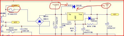
Now measure the plus 11 volt supply which you can find on one end of D521. The other end of the diode should have 8 volts.
Thats your first step. Are those two voltages correct.
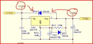
If they are, then you need to see if the 11 volts is reaching U502. Again we can easily measure on the diode D516. There should be 11 volts on one end and 5 volts on the other.
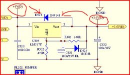
Again if that is OK then we now move to U507 and again by measuring on diode D525 we should see 5 volts on one end and 3.6 on the other.
Report back with your readings (and don't forget the fuses)
Look at the PSU on page 8 of the manual.
Connect the negative lead of your meter to any ground point such as the audio output ground on theaudio output phono socket. Yes
Now measure the plus 11 volt supply which you can find on one end of D521. The other end of the diode should have 8 volts.
Thats your first step. Are those two voltages correct.
If they are, then you need to see if the 11 volts is reaching U502. Again we can easily measure on the diode D516. There should be 11 volts on one end and 5 volts on the other.
Again if that is OK then we now move to U507 and again by measuring on diode D525 we should see 5 volts on one end and 3.6 on the other.
Report back with your readings
(and don't forget the fuses)Attachments
Hope this is of some help to you. I have been using this reg. for many years and I have never experienced one that has failed. That is, following the datasheet.
http://www.ee.buffalo.edu/courses/elab/LM117.pdf
http://www.ee.buffalo.edu/courses/elab/LM117.pdf
Where next
We do more checks on the PSU and confirm ALL the other rails are OK too. If you look at the circuit you will see three more regulators each with a diode across it that makes it easy to measure the voltages just like before. The difference here is that U504 and U505 are fed from a relay and so this means the player must be fully ON (not in standby) to measure these.
So you should have plus and minus 12 volts as "switched" supplies that appear only when the player is fully on and also a minus 30 volt supply.
So confirming all these rails are correct is the next step.

Hi Tom,
I'm on 'tother PC without the circuit...
The plus and minus -12 look OK, thats U504 and U505.
The minus 30 again looks OK although no real differential between input and output... I'll have to look at the circuit for that.
U506. Again I'll have to look at the circuit. The numbers look OK although tbh I don't remember just seeing another 5 volt reg.
Wait 'till I have the circuit, but all seems reasonable up to now.
All those look OK Tom although I am puzzled at the minus 30 volt rail (although its only for the display) because there should be a "more than minus 30" going into the reg. The manual shows it as a minus 30 volt regulated rail value so the reg would need at least minus 35v ish to work properly. Thats the junction of D505 and D523. Even if there is a problem there it shouldn't affect the rest of the player.
Don't know how I missed U506... but your reading is spot on.
Have we checked U502. I've lost track of all these. Its another 5 volt rail.
If that checks out then we can be pretty sure the PSU is OK. So what fault are you actually seeing now ???
I assume the player powers up OK, display lights and the tray opens and closes correctly.
We probably covered this in the other thread but does the lens move up and down 3 or so times when the tray is closed and no disc inserted ?
If you unplug the machine and manually move the sled away from its normal rest position near the centre of the disc and then switch on does the sled move back to rest position ?
Don't know how I missed U506... but your reading is spot on.
Have we checked U502. I've lost track of all these
. Its another 5 volt rail. If that checks out then we can be pretty sure the PSU is OK. So what fault are you actually seeing now ???
I assume the player powers up OK, display lights and the tray opens and closes correctly.
We probably covered this in the other thread but does the lens move up and down 3 or so times when the tray is closed and no disc inserted ?
If you unplug the machine and manually move the sled away from its normal rest position near the centre of the disc and then switch on does the sled move back to rest position ?
arcam cd 73
hi, U502 readings were: 10.80/5v respectively.
Still showing no disc error on display, even with disc in,everything operates as normal and yes, laser does move up/down approx 3 times,also moves to rest position if moved before power up, only thing I can't see is any light from laser?
Can I assume been sent a duff replacement laser from ebay seller,as with the replacement in, it was making weird high pitched noises on power up and there was no rotation of cd with replacement in situ,I am now running on original unit(which may also be duff)?
I have now located a seller selling(reportedly) genuine stamped sony lasers not unbranded item that I have in my possession,do you think it would be worth trying a new sony laser?
The workhop manual suggests looking at microswitches, although I can't see anything like this near mechanism?
many thanks,
tom.
- Status
- This old topic is closed. If you want to reopen this topic, contact a moderator using the "Report Post" button.
- Home
- Source & Line
- Digital Source
- lm 317t voltage reg