I am puzzled about the SONY current pulse DAC principle, which
they use in a number of both CDPs and SACDPs. First there is
a chip (differes between players) labelled as DSP and DAC.
Fair enough. However, after this comes another chip also
called a DAC, the so called current pulse DAC. Further more,
the first DAC has two (balanced?) pairs of outputs per channel
going into the current pulse DAC, the latter having the usual
balanced pair of current outputs.
First, the terminology seems misleading. After a DAC we have,
by definition, an analog signal, which is pointless to feed into
a DAC which expects a digital signal. I thus assume the second
chip isn't quite a DAC, although called so, but what does it do?
Also, why are there two pairs of outputs from the first DAC? I
understand that, at least in the SACD players, it is possible to
use the signals from only one of these pairs and bypass the
current pulse DAC. I also understand it is possible to bypass it
and use both pairs from the first DAC and somehow crosscouple
them. Can somebody shed some light upon why there are two
pairs of outputs and also what the current pulse DAC does?
This is SONY's own explanation of the Current Pulse Converter. ...
Sony’s engineers for the "Extremely high Standard" (ES) series created other decisive factors for excellent sound quality: the Current Pulse D/A Converter and R-Core Transformer. Unlike standard D/A converters, the new Current Pulse D/A Converter does not use a voltage-pulse output. Instead it operates with current-pulse output for constant signal quality. Changes in voltage amplitude (e.g. from mains fluctuations) are eliminated and harmonic distortion is minimised. The R-Core Transformer on the other hand ensures a stable voltage supply independent of load.

Sony’s engineers for the "Extremely high Standard" (ES) series created other decisive factors for excellent sound quality: the Current Pulse D/A Converter and R-Core Transformer. Unlike standard D/A converters, the new Current Pulse D/A Converter does not use a voltage-pulse output. Instead it operates with current-pulse output for constant signal quality. Changes in voltage amplitude (e.g. from mains fluctuations) are eliminated and harmonic distortion is minimised. The R-Core Transformer on the other hand ensures a stable voltage supply independent of load.
in other words: might it be that this are simple R2R DAC´s??
anyway.... what a stupid definition: "Instead it operates with current-pulse output for constant signal quality. Changes in voltage amplitude (e.g. from mains fluctuations) are eliminated and harmonic distortion is minimised" ????
I did no further investigation on that, but what I think is that this is another marketing gag, like they do with oversampling...
Lars, thanks, but I am afraid that doesn't help much. It sounds like
some crap from the Sony marketing department mostly. Do
you manage to get something useful out of it?
I would expect, however, that you know more about it, since
you do tell your customers how to connect the zapfilter to
the first DAC, skipping the current pulse one. (A friend of mine
recently installed one according to your instructions).
I can only speculate based on that Sony text, but I get the
impression the first DAC gives voltage out, the current pulse
DAC converts this to current out which is then converted back
to voltage in the ususal I/V converter (talking about Sony
original now, not you Zapfilter). That seems not to make
much sense, but I am no DAC expert. However, since the
first DAC outputs two pairs of signals per channel, and they
talk about rducing mains fluctuations, maybe there is some
trick here that is not immediately apparent?
Please note, I am not intending to discuss the Zapfilter here, I
am only wondering about the Sony double DAC scheme.
I am just working on this exact subject.
Yesterday evening I installed a parallel analog stage in my Sony CDP-XB930 player.
I left the original current pulse DAC part + old analog stage as is for the moment and just took additional output after the first voltage output DAC. This additional output is feed to 3rd order LP filter formed around Borbely Super Buffer circuit....
*The double differential DAC is working in a way that when one voltage pulse output is going 0 -> 1 then there is always an other one going from 1 -> 0. This creates an effect that there is always a similar current drawn from supply lines and all in all it creates less garbage on DAC supply lines. (The credit for the explanation goes to my friend Sulo)
**I have been planning the mod I just did for about half a year. You are not the only one who sees pointless complication of things with current pulse DAC. Whatever they gain with converting the voltage pulses to current pulses they most surely add problems with increased jitter, more contamination on power lines and more complicated analog stage needed for the latter (or at least Sony's version is more complicated)
***
Anyway, I have now a player that has a 100% original output + the modded output where the signal is taken out of the player right after the voltage ouput DAC. I made thing deliberately this way, so I would be able to compare the two.
Next steps that I will be taking next (bigger ones)
* separate power supply for new analog stage (at the moment the Borbely Buffers use +/- 12V analog supply from the players main board)
*To install a Guido Tent XO2 clock
*To try my own active circuit instead of Borbely Buffer (I was planning this from the beginning but the JFET order for this is long delayed by supplier...)
I started the way I did because I tought I needed a very good analog stage first and then the power supply tweaks, clock change etc. I'm guite sure that with original analog stage one can't hear all the small nuances of improvement brought by changes in supply and clock and so on.
****
Anyway, in near days I will hopefully have a chanche to really listen and compare the results and I will write comments here if anyone's interested...
Ergo
Ergo,
thanks a lot for the explanation, it makes a lot of sense.
Just one question, when you talk about the two complementary
signals, I assume both of these are balanced, that is, one of
the two pairs is a balanced signal going from 0->1 and the
other is a balanced pair going from 1->0 (or the other way
around, of course). This is interesting since it is related to
several other threads on designing
amplifiers so they draw a constant current.
BTW, I have an CDP-XB920, which I assume is very similar
to yours?
A friend of mine has the SACD 555 model, which uses the
same scheme, although with different chips. He recently
implemented a Zapfilter, taking the output from the first
voltage-output DAC. He first tried a variant he found on the
net recommended by someone in Hong-Kong, which used
only one of the signal pairs and connected this directly to
the Zapfilter with no filters in between. He then decided to
instead try the variant recommended by LC, which uses
both pairs of signals, but I didn't quite get his explanation of
how they were connected together to form one balanced
signal. This variant also uses a passive filter inbetween.
My friend clearly preferred the latter variant.
Christer,
http://www.vacuumstate.com/Kits.htm
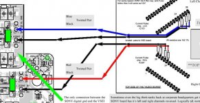
This is the screenshot from Allen Wright's datasheet for his upgrade module installation guide (could not find it from his website anymore)
As you see the signal is taken out with 4 resitors for both channels and the other ends of the resistors are connected in pairs. Allen uses 1k2 resistors and 2n2 capacitor on the other end of twisted pair wires.
I used 6040 ohm resistors and 100p capacitor soldered directly to resitor pins.... and then I took a single end signal between gnd and one end of the cap as my analog stage is not balanced at the moment.....
http://www.vacuumstate.com/Kits.htm
This is the screenshot from Allen Wright's datasheet for his upgrade module installation guide (could not find it from his website anymore)
As you see the signal is taken out with 4 resitors for both channels and the other ends of the resistors are connected in pairs. Allen uses 1k2 resistors and 2n2 capacitor on the other end of twisted pair wires.
I used 6040 ohm resistors and 100p capacitor soldered directly to resitor pins.... and then I took a single end signal between gnd and one end of the cap as my analog stage is not balanced at the moment.....
Attachments
ErgoErgoErgo!
DON'T STOP, PLEASE!
What did happen at the end? What was the final soundimpression? Made it balanced or not?
I am also with an XB-930, willing to tweak it. First I aimed the Nelson Pass' D1 I/V stage. Now I hesitate, your experience is something new to me.
Do you have some service diagrams of the player, too? Or this presented snapshot is the only?
Continue, please!
Laci
At the moment I still have my player at the same state due to total lack of time for DIY activities as there is a big campaign is Estonia for our national identity cards and as I'm responsible for the production I have some really busy times.
Anyway, the setup as it is at the moment is a 3rd order LP filter built around Borbely "Super Buffer". The signal comes straight from voltage output DAC (the first IC). The power supply is the same as the original analog supply and also the old analog stage is operative for comparison.
Already this has resulted a much better and likeable sound. No tiring graininess which is present in original output. The sound is very well balanced and seems "right" in all respects. I mean all the instruments sound as they are supposed to etc.
What the sound is still lacking is dynamics and 3D soundstage. Both are there but not as good as it can be....
***
Plans that I have in future include
*power supply upgrade (separate transformer and totally different voltage stabilisation)
*my own analog stage idea (already got even the PCB's but have not soldered it together yet)
*clock upgrade (TENT XO2 waiting on the shelf also)
* hundred other small tweaks (but not before I can really hear the change in sound, meaning all the previous points implemented.
***
I will sure post the results on the forum as soon I get some progress
Rgds,
Ergo
For historical purpose only, I reincarnate this old thread because I think I inadvertently found a Sony patent which describe the purpose, meaning and operation of what seems to have become the Current Pulse DAC.
I'ts Takashi KANAI & Toshihiko MASUDA 5,343,197 US patent : Patent US5343197 - Digital-to-analog converter - Google Patents
Regards.
I'ts Takashi KANAI & Toshihiko MASUDA 5,343,197 US patent : Patent US5343197 - Digital-to-analog converter - Google Patents
Regards.
- Status
- This old topic is closed. If you want to reopen this topic, contact a moderator using the "Report Post" button.
- Home
- Source & Line
- Digital Source
- How do SONY current pulse DACs work?