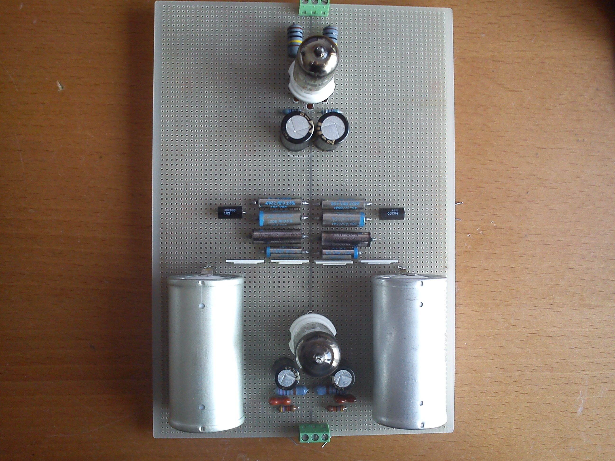
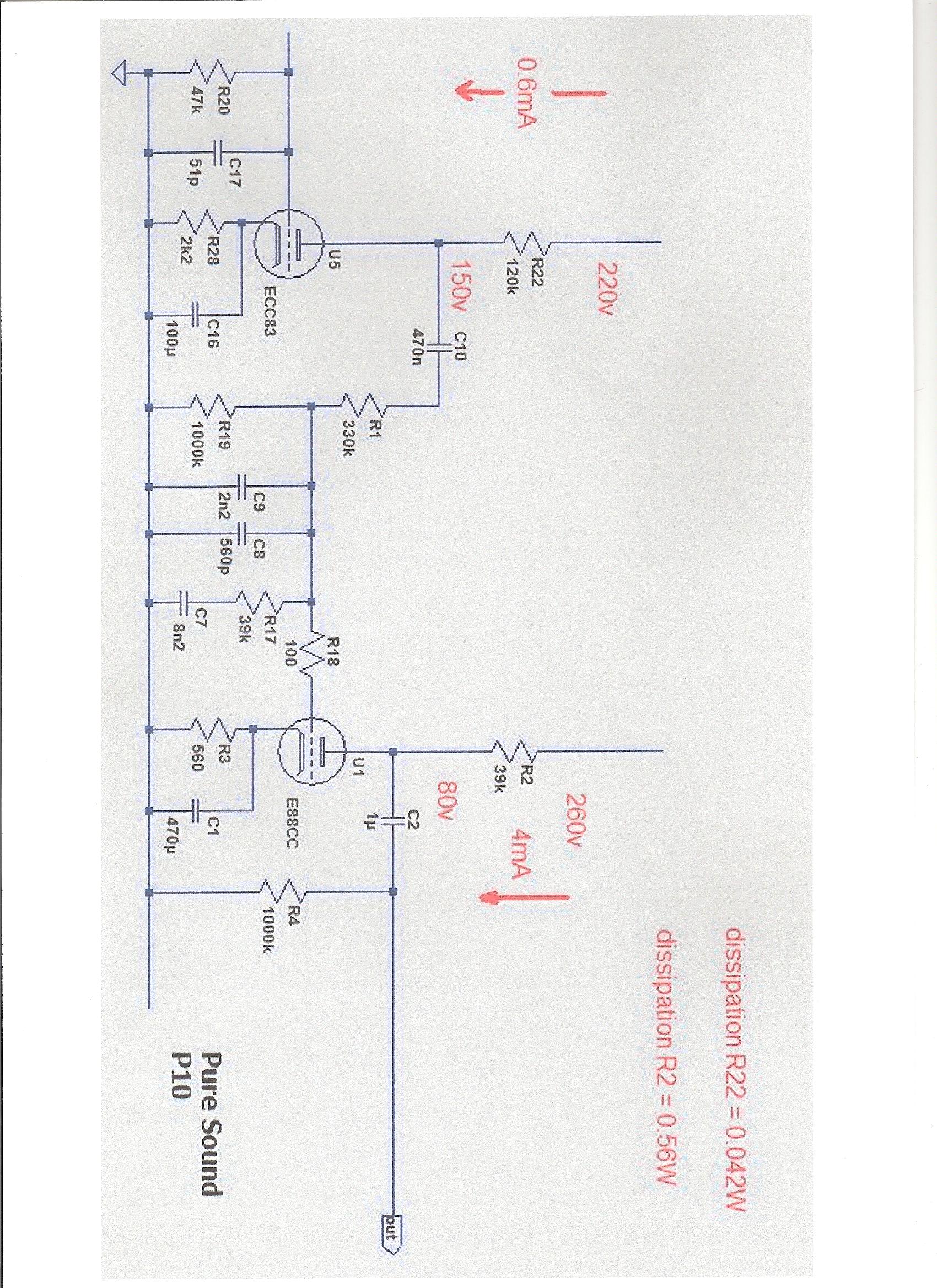
I'm open this new thread to fine tune my Puresound P10 phono RIAA, also I would like to know output impedance of first stage? schematics & real unsoldered components values as follows:
Left channel
R1 329K CADDOCK TF020R
R19 998K CADDOCK TF020R
C9+C8 .00270 paralleled .000106 = 2.806nF teflon film & aluminium foil
R17 38K9 CADDOCK TF020R
C7 .006 paralleled .0022 = 8,2nF teflon film & aluminium foil
R18 99R9 SHINKOH
Right channel
R1 329K CADDOCK TF020R
R19 999k CADDOCK TF020R
C9+C8 .00270 paralleled .000106 = 2.806nF teflon film & aluminium foil
R17 38K9 CADDOCK TF020R
C7 .006 paralleled .0022 = 8,2nF teflon film & aluminium foil
R18 99R9 SHINKOH
Any help will welcome.
Based on the info here: On 'RIAAEqualization Networks´ and following Lipshitz calc I devised a simple simulator. http://forums.melaudia.net/attachment.php?aid=1301
Excluding the effect of first stage output impedance and also the miller of the second stage, my initial test would be to use:
R17 = 38K9 // 478K = 35973 r
C9//C8 = 2.7nF // 106pF // 220pF = 3.026nF
C7 = 6nF // 2.2nF // 640pF = 8.84nF
Let me know what real values you can get so we can choose the best options.
Of course, all must be recalculated if there is significant output impedance on the first stage and we should also consider miller effect of second stage (I do not know if there is any "forward" miller from the first stage also).
I hope we can get enough input here to come to a consensual result.
Regards
Ricardo
Last edited:
My assumptions are based on the results of enumerous experiments with Salas Simplistic.
IMO, the 500,5Hz "zero" pole is of fundamental importance to the correct reproduction of the instruments timbre.
> 500,5 Produces less attack
< 500,5 Results in more nasal sound with more attack
= 500,5 Provides perfect Instrument Timbre
According to the simple formula f = 1 / 2pT
500.5Hz corresponds to 318uS time constant
This 318uS is what I am aiming to.
In this case we have R17 = 35973 ohm and C7 = 0.00884uF
R17 x C7 = 318.0013 Very close to 318.
The low frequency pole 50.05Hz and the high frequency 2122Hz are also corrected by my simulator but these depend on the impedance and miller effect on the amplifying stages.
Similarly to the Simplistic, these SE no NGF designs are much more difficult to implement than the active riaa using feedback as is very well explained here : Audio Gadgets: RIAA Equalization
>>Quote:
Active EqualizationThe advantage of the feedback approach is consistency. Each channel will track the other to a very great degree in spite of aging parts or circuit wiring dissimilarities, as the feedback tends to iron everything out. The disadvantage is that because it is active, it can suffer from voltage overload and instability. Additionally, the varying amount of frequency dependent feedback can result in looser bass reproduction because of smaller amount of feedback at low frequencies and possibly a pinched, compressed high frequency playback due to excessive feedback ratios.
Passive EqualizationPassive RIAA equalization means brute force equalization: the frequency response is tailored to fit that of the RIAA curve by varying the amount of attenuation at different frequencies through a complex RC network. The advantages: no voltage overload, no feed-back, no instability problems. The disadvantages: no gain, insertion loss, impedance matching problems.
End of quote<<
IMO, opamp based Riaa preamps always sound compressed in the high frequencies (due to high feedback ratio)
The simpler SE designs let the sound flow very naturally. Of course, due to the absence of global NFB, these are much more difficult to implement with the same low distortion levels.
Anyway, in a jfet SE input, distortion is mainly 2nd, presenting much lower 3rd than an equivalent differential input.
Also, as there is no global NFB, psrr is quite high so the psu is also very important here.
These SE designs respond very well to psu output impedance tuning.
Last edited:
I learned a lot because I wanted to understand the differences between the several EQ available (RIAA, IEQ, Columbia, EMI, etc...)
I followed some good threads in this Forum")
http://www.diyaudio.com/forums/analogue-source/158911-parasound-jc3-phono.html
http://www.diyaudio.com/forums/analogue-source/188578-diy-phono-stage-gives-great-results.html
http://www.diyaudio.com/forums/analogue-source/188876-riaa-equalization-standard.html
I followed some good threads in this Forum
http://www.diyaudio.com/forums/analogue-source/158911-parasound-jc3-phono.html
http://www.diyaudio.com/forums/analogue-source/188578-diy-phono-stage-gives-great-results.html
http://www.diyaudio.com/forums/analogue-source/188876-riaa-equalization-standard.html
Last edited:
"Excluding the effect of first stage output impedance and also the miller of the second stage
Of course, all must be recalculated if there is significant output impedance on the first stage and we should also consider miller effect of second stage (I do not know if there is any "forward" miller from the first stage also)."
I asked all your questions to the Mr. Gay designer/manufacture Pure Sound P10.
Puresound P10 tube phono RIAA
I posted this thread in Analogue Source but I want to post here because it's a tube phono preamp, link to thread:
http://www.diyaudio.com/forums/analogue-source/190613-puresound-p10-riaa.html
I posted this thread in Analogue Source but I want to post here because it's a tube phono preamp, link to thread:
http://www.diyaudio.com/forums/analogue-source/190613-puresound-p10-riaa.html
For E88CC I found the following values (Hope these are ok as my German is very bad) :
Grid to Cathode 3.1pF
Grid to Plate 1.4pF
Miller 25 x 1.4 = 35pF
Total = 38.1pF
This is a very small value and will not introduce any nasties in the C8//C9 combo.
Anyway we can use C9//C8 = 2.7nF // 106pF // 180pF // .0381pF = 3.024nF
Now we just need input about first stage output impedance.
Grid to Cathode 3.1pF
Grid to Plate 1.4pF
Miller 25 x 1.4 = 35pF
Total = 38.1pF
This is a very small value and will not introduce any nasties in the C8//C9 combo.
Anyway we can use C9//C8 = 2.7nF // 106pF // 180pF // .0381pF = 3.024nF
Now we just need input about first stage output impedance.
For E88CC I found the following values (Hope these are ok as my German is very bad) :
Grid to Cathode 3.1pF
Grid to Plate 1.4pF
Miller 25 x 1.4 = 35pF
Total = 38.1pF
This is a very small value and will not introduce any nasties in the C8//C9 combo.
Anyway we can use C9//C8 = 2.7nF // 106pF // 180pF // 38pF = 3.024nF
Now we just need input about first stage output impedance.
So I only have to add 218pF in each channel
Last edited:
I would determine that resistor value experimentally- in that design, the ECC83's output resistance is very significant and is likely to vary quite a bit from tube to tube. Measure the output of the preamp at 50Hz and 1kHz. If the difference is less than 20dB, add a bit more resistance. If it's more than 20dB, reduce the resistance.
As the preamp tubes age, the RIAA conformance will drift. That's a serious issue with any design that has a high rp tube feeding a passive RIAA filter.
As the preamp tubes age, the RIAA conformance will drift. That's a serious issue with any design that has a high rp tube feeding a passive RIAA filter.
So I only have to add 218pF in each channel
No
You only need to add 180pF because the 38pF are coming from the second stage Miller.
I would determine that resistor value experimentally- in that design, the ECC83's output resistance is very significant and is likely to vary quite a bit from tube to tube. Measure the output of the preamp at 50Hz and 1kHz. If the difference is less than 20dB, add a bit more resistance. If it's more than 20dB, reduce the resistance.
As the preamp tubes age, the RIAA conformance will drift. That's a serious issue with any design that has a high rp tube feeding a passive RIAA filter.
I agree with you but just as a starting point, what would be the 1st stage output impedance ? (Let us know your best guess please).
How can we make the first stage less dependent of tube ageing ?
How can we make this design less dependent of this tube rp ?
PS: reading this: TUBES: its RP, not MU, that's important! [Archive] - The Gear Page gave me a starting point relative to rp importance.
Well, those values are so high that if I try to include them im my simulator (excel calculator), It produces big errors to riaa.
The highly tuned design in attach is very similar to the Puresound, appart from the plate resistor that is 5k against the 120k in the Puresound.
It seems to me this schematic also disregards the effect of the the first stage output impedance so I would have a go with the values already determined.
Merlin... The circuit you need to tune is already built ?
We need some subjective listening impressions now.
Attachments
- Status
- This old topic is closed. If you want to reopen this topic, contact a moderator using the "Report Post" button.
- Home
- Source & Line
- Analogue Source
- Puresound P10 RIAA