First, been browsing for a bit and this is a great site. Now onto the issue at hand.
First I'm an EE major and we are required for a semester project to build an audio device that consists of a lot of requirements which I won't go over here.
The power amplifier stage is required to be a Class AB amplifier with between 3W and 25W of output power and a THD < 1%. While breadboarding I had issues with thermal runaway and asked the professor for suggestions. Where upon he gave some horrible advice to remove the rubber diode I was using to bias the power transistors and simply feed the output of the emitters from the power transistors through the feedback loop of the opamp (essentially having the opamp handle the biasing of the transistors). Now the design works fine in simulation of course, but I have to wonder if it is even possible to meet the THD requirement without the rubber diode (or regular diodes) if quality opamps are used?
I'm not looking for high quality audio just to meet the requirements for right now. If funds and time allow I may come back and make a better design but if what I have will work then I need to move on to other parts.
I appreciate any insights, insults and inferences.
Sure,
Here's the schematic (after the professors suggestion):
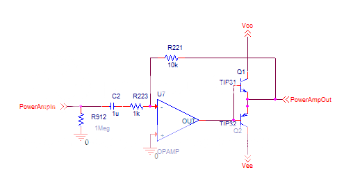
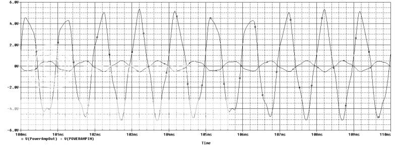
My previous design was the same but with a 3904 used to create a bias voltage on the power transistors. Here's the simulation (the input is not a sin wave). It works fine but this is with an ideal op amp so the slew rate is infinite:
The opamp I'm planning on using is a OPA134.
Here's the schematic (after the professors suggestion):
My previous design was the same but with a 3904 used to create a bias voltage on the power transistors. Here's the simulation (the input is not a sin wave). It works fine but this is with an ideal op amp so the slew rate is infinite:
The opamp I'm planning on using is a OPA134.
The power amplifier stage is required to be a Class AB amplifier with between 3W and 25W of output power and a THD < 1%.
I'm not looking for high quality audio just to meet the requirements for right now. If funds and time allow I may come back and make a better design but if what I have will work then I need to move on to other parts.
I appreciate any insights, insults and inferences.
You should be able to meet these criteria quite easily with a fairly simple design and have it sound decent without breaking the bank. For the more expensive items like power transformer, heatsink and filter capacitors you can reclaim used parts from other dead equipment, the rest should be readily available and inexpensive.
Post your current schematic and perhaps get some ideas off the board. Have you consulted any published resources from Bob Cordell, Dougls Self or Randy Slone? Any of these would be a good starting point for an introduction to class AB amplifier design.
Ok, I started reading up more and this appears to be a class B push-pull amplifier if I am not mistaken? What exactly is the difference between a class AB and a class AB push-pull? If I am reading it correctly then the dc biasing of the transistors that place them into forward active region is what makes them the class AB.
I apologize for my ignorance in this subject, I'm much better with a MCU.
I apologize for my ignorance in this subject, I'm much better with a MCU.
OK, so the opamp is basically required to slew through the output buffer transistors crossover region where they aren't conducting quickly enough to avoid serious crossover artifacts. This actually works with a sufficiently fast opamp. This would be is the strictest sense actually closer to class C as the OPS has a relatively broad area of non-conduction.
There ia no real true class B as device physics do not allow exactly 180 degrees of conduction per output device. An 'optimally biased' arrangement is often called a class B design and has a relatively modest bias current. Increasing the bias to produce a broader region of mutual conduction results in a class AB design where a small amout of the amps output is class A and beyond that the outputs cut off alternately with the signal, a-la class B. Really jacking up the bias results in a class A amp where the output devices are always in the linear region and never cut off or saturated. Class AB or B will always be 'push-pull', class A can be 'single ended' or 'push pull'.
Is the opamp required in the design? Could you handle something fairly simple that is a discreet design? If the opamp is a required part of the design I'd suggest using it as the amps IPS and using a conventional discreet VAS and OPS.
For a simple discreet, look at something like this: It can give you power at the upper range you are looking for with signifigantly less distortion than you are allowed. The diodes would be mounted to the heatsink to stabalize bias. You could sub those with a Vbe multiplier, but the goal is as dead simple as possible with reasonable utility and performance.
Attachments
This is starting to make a lot more sense now. It sounds like the op amp feedback design will work, the opamp I choose has a very good slew rate so that should help.
In regards to the schematic jkuetemann posted, what is the advantage of using a diferential amplifier for the gain and feedback stage as oposed to an opamp? I've seen a lot of designs that used that but always thought that opamps provided a more linear gain and they have a differential amplifier as the output stage anyways.
In regards to the schematic jkuetemann posted, what is the advantage of using a diferential amplifier for the gain and feedback stage as oposed to an opamp? I've seen a lot of designs that used that but always thought that opamps provided a more linear gain and they have a differential amplifier as the output stage anyways.
If the design criteria is to be class AB, then the circuit in post 3 will not cut it. For class AB the output devices must have some bias. This complicates things because you now run into thermal vs transconductance issues, and in particularly with BJTs the reduction of Vbe vs temperature, which can also be expressed in conductance.
BTW, at what impeadance does this 3-25W amp need to drive? Is there any specific criteria for the devices you can use? If there are no restrictions, I would suggest you look into the 'Thermaltrack' BJT output devices from On-semi. A simple bias arrangment for the outputs following an op-amp would be my suggestion. Granted they are capable of more power than your goal, but it would simplify things quite a bit. Mr Cordell has plenty of information about these devices in his book....not hard to reference here at this site.")
BTW, at what impeadance does this 3-25W amp need to drive? Is there any specific criteria for the devices you can use? If there are no restrictions, I would suggest you look into the 'Thermaltrack' BJT output devices from On-semi. A simple bias arrangment for the outputs following an op-amp would be my suggestion. Granted they are capable of more power than your goal, but it would simplify things quite a bit. Mr Cordell has plenty of information about these devices in his book....not hard to reference here at this site.
Ya I realized it's not a class AB, my professor is however has no knowledge of what he is teaching, most of the TA's I've had are much more knowledgeable. The load is 8ohms. Those thermaltrak transistor/diode pairs are pretty cool, the entire project has to have a BOM of less then $150 however and $20 for power transistors alone plus a bit more for heatsinks is a little too much, added it to my bookmarks though. My opamps are coming in today and I'll let everyone know how the initial design works.
What exactly is the difference between a class AB and a class AB push-pull?
I apologize for my ignorance in this subject, I'm much better with a MCU.
What are they teaching in EE school these days? They should have explained this way before now.
Class A: DC= 360 deg; Class App: DC= +/-360 deg
Class B: DC= 180 deg; Class Bpp: DC= +/- 180 deg
Class C: DC < 180 deg; Class Cpp DC < +/-180 deg
Class AB: 180 deg < DC < 360 deg; Class ABpp: +/-180 deg < DC < +/-360 deg
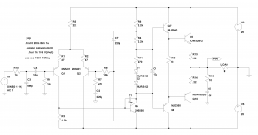
Your "perfesser" is an idiot. This is absolutely hideous! Here's a design I did for the audio strip for a longwave receiver. You can see here how to do a power amp design right. This particular final is just what you want: it's push-pull, and it's Class AB. Unlike that monstrosity your "perfesser" suggested, it sounds quite good, despite the fact that I wasn't designing for Hi-Fi, as this is a communications receiver, where fidelity is not necessary, and where it's not possible with a DBM anyway. 99.9% of longwave work is done in CW anyway, so it doesn't matter.
Attachments
If this is to be a "ClassAB" amplifier it really falls on the first count because it isn't
The definitions as used tend to get blurred ,but a design such as this with zero quiescent current is what many would call Class B or under biased Class B.
My thoughts,
I guess simplicity is the order of the day here so what can be done to optimise this design.
As to the design itself. I would use an opamp with plenty of "drive capability" such as a 4560 although most devices will work. Use transistors with a high current gain (hfe). The TIP31/32 are not outstanding in that regard. And the killer component... a low value resistor added between B and E of the outputs such that at levels below the turn on voltage of the transistors the opamp supplies the load.
Ultimately it's a crude circuit but it can be optimised by careful design.
I would also question why it needs to be inverting too. The input impedance is set by the 1K resistor which is way to low for a normal audio amp. Also the low frequency response is determined by the combination of C2 and R223 which form a high pass filter.
I tend to agree with Mooly. What's not needed is a hatchet job on the professor or the circuit in question by all the resident geniuses. This is a college student looking for a bit of help on his project. With a bit of tweaking, this circuit is perfectly ok for a project write up.
Better to be welcoming and supportive than to swing the mace and turn another potential analog engineer into a digital jockey through a bad attitude. We have more than enough of those around.
Better to be welcoming and supportive than to swing the mace and turn another potential analog engineer into a digital jockey through a bad attitude. We have more than enough of those around.
Last edited:
You should use 2 diodes to bias transistor.
LIke in the Miles Prower circuit here: http://www.diyaudio.com/forums/atta...-ab-amplifier-new-analog-world-audiostrip.gif
LIke in the Miles Prower circuit here: http://www.diyaudio.com/forums/atta...-ab-amplifier-new-analog-world-audiostrip.gif
Here, try this.
I've numbered the components for ease of discussion.
Class AB and good enough for 8-10W of power and with a decent general pupose unity gain stable op-amp the power bandwidth will be about 40KHz.
with a bit of optimization you should easily be able to get <0.2% distortion.
Use a TL071 - unity gain stable op-amp.
Good luck
Attachments
Last edited:
I had a friend that had to do the same project when he was EE school.
He had used TIP 1xx darlingtons for the output.
I don't remember which ones he used but TIP 120 and it's complement seems to ring a bell.
I remember he said he got about 30 or 40 watts out of it and the distortion was quite low.
I was going to build one but never did.
Thats all I can remember about it since 1982.
In circuit maker I once did the same circuit and had adapted a pair IRF 510's for the output but I can't find it otherwize I would post it for you. jer
Last edited:
Here is the link to the rane headphone amplifier that I had mentioned. jer
HC 6S Headphone Amplifier
HC 6S Headphone Amplifier
I've seen a lot of designs that used that but always thought that opamps provided a more linear gain and they have a differential amplifier as the output stage anyways.
That design is a very simplistic opamp in itself, with the ability to drive the output directly. I does suffer from higher input bias requirements (lower input impedance) than an actual opamp. Some form of differential input is quite common as it provides really convenient nodes for input and feedback and helps reduce dependance on individual device characteristics. There is nothing special about the transistors I've shown, a few general purpose small signal devices and a pair of mid-power drivers and your choice of outputs. You could use your TIP31/32 for drivers and 2N3055/2955 for outputs if you like, they are cheap and readily available. Some resistor values have to be adjusted for significantly different supply voltages if the same quiescent currents are to be maintained, but the design is simple and solid.
A simple band aid...
What I'm about to propose isn't as nice as the proper biasing methods shown by other forum members, but it's sometimes handy in a pinch. The problem is that in the crossover region, the output transistors have no gain at all. Well, if your opamp is something like a 5534, that can drive some current, you can place 50 Ohms (1 resistor) between the based and emitter of the output transistors. Now, when the opamp output is less than +/-0.6, there is at least some gain (8/58) in the output stage. It's not perfect by any means, but 8/58 is a lot more than zero. Experiment with, simulate it, and think about the value, and come to understand its limitations compared to some of the more usual biasing schemes. Under the right set of conditions, it's not a bad answer.
What I'm about to propose isn't as nice as the proper biasing methods shown by other forum members, but it's sometimes handy in a pinch. The problem is that in the crossover region, the output transistors have no gain at all. Well, if your opamp is something like a 5534, that can drive some current, you can place 50 Ohms (1 resistor) between the based and emitter of the output transistors. Now, when the opamp output is less than +/-0.6, there is at least some gain (8/58) in the output stage. It's not perfect by any means, but 8/58 is a lot more than zero. Experiment with, simulate it, and think about the value, and come to understand its limitations compared to some of the more usual biasing schemes. Under the right set of conditions, it's not a bad answer.
- Status
- This old topic is closed. If you want to reopen this topic, contact a moderator using the "Report Post" button.
- Home
- Amplifiers
- Solid State
- Class AB Amplifier - New to the analog world