After the JLH, the Chtringlunator and the Voltage Regulator Chip Amp, here comes the Circlo, Half-Diamond Unity Gain Buffer, another "funny amplifier".
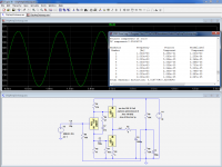
It operates in class A, and as usual, R2 can be halved with real LM317's.
The simulated and measured distortions are in perfect agreement.
As a bonus, the complementary regulators half diamond topology has a negligible in/out offset voltage.
It operates in class A, and as usual, R2 can be halved with real LM317's.
The simulated and measured distortions are in perfect agreement.
As a bonus, the complementary regulators half diamond topology has a negligible in/out offset voltage.
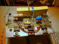
Attachments
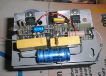
You can easily parallel a number of them by inserting a small resistor (~0.1ohm) in each output terminal.
In the circuits where a resistor already exists (current sources, etc, ), you just have to duplicate the resistor+regulator the number of times required.
Will this lead to a 1KW voltage reg chip amp?
On a 0.2 ohm load then, unless you (or I) find a way of series-connecting them for increased voltage output.
The next project maybe.....
Really fanny, i want to try too, one of this.
I have few questions:
Is it amp with gain or just buffer?
If there is gain, how much and how to calculate?
Max output power? (with 1 pair in output)
Can I power this amp with PS build on pair LM317/337 to max output?
The same questions about JLH amp, especially about gain.
I have few questions:
Is it amp with gain or just buffer?
If there is gain, how much and how to calculate?
Max output power? (with 1 pair in output)
Can I power this amp with PS build on pair LM317/337 to max output?
The same questions about JLH amp, especially about gain.
This one is just an accurate unity-gain buffer, and it operates in class A (you need sufficient heatsinks, but one good thing about voltage regulators, they will shut-down if the temperature rises too much. Heatsinks are therefore much less critical than for a traditional class A).
This one is also in class A, but it has gain, and is a complete amplifier:
http://www.diyaudio.com/forums/chip-amps/176052-now-regulator-chip-jlh-amp.html
The Chtringlunator is a unity gain output stage for headphones.
http://www.diyaudio.com/forums/chip...oss-tringlotron-regulator-chip-amplifier.html
It could be preceded by the voltage amplifier of the Tringlinator to make a complete (and completely exotic) headphone amplifier.
http://www.diyaudio.com/forums/headphones/165131-tringlinator-mos-based-tringlotron-amplifier.html
This one is also a complete amplifier, operating in class B:
http://www.diyaudio.com/forums/chip-amps/175457-just-fun-regulator-chip-amplifier.html
To alleviate the slew rate problem, R9 can be shorted to increase the quiescent current.
Further increase in the Iq could be obtained by using a lower voltage reference than the LT1009 or LM336: an adjustable 1.2V ref, wired for 2V for example.
The gain calculation is similar to a normal amplifier: for the Regulator-Chip Amplifier, it is 1+R6/R11, and for the JLH it is R7/R6.
The standard regulators limit the current to 1.5A^, that is ~1Arms. That's about 8W on 8R load.
You can off course use voltage regulators to power them
The maximum output power attainable by pushing the total supply to 40V and using a number of parallel pairs in a BTL configuration is ~140W on a 4R load.
This requires 2 groups 6 pairs minimum, that is 24 devices. In practice, to deal with complex loads, etc, 8 pairs minimum would be preferable to reach 125W realistically.
A bit parts-intensive, but the resulting amplifier would be exceptionally robust.
This requires 2 groups 6 pairs minimum, that is 24 devices. In practice, to deal with complex loads, etc, 8 pairs minimum would be preferable to reach 125W realistically.
A bit parts-intensive, but the resulting amplifier would be exceptionally robust.
What purpose are for R2,R9 instead of one resistor and input, output grounds to ground?
It is an attempt to balance the current swings of the two output devices:
The total value of R2 + R9 cannot go below approx. 1.6 ohm (1.25V/0.75A).
This imposes the effective transconductance of the lower device.
Balancing can then be made by correctly dimensioning R4 wrt. R3, but a relatively large R4 would be required, leading to a diminished negative voltage swing.
Splitting the resistance between R2 and R9 gives one more degree of freedom, and enables a symmetrical swing without the limitations.
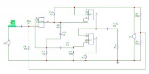
You mistakenly made R2 a 4.7 ohm instead of R8. Should be the other way round.
I don't think C1 = 1µ is a good idea, it would upset current sharing at lower freqs. Not a conventional signal path coupling cap, this one. Change C4 instead.
R31 should have at least 10 µF in parallel, 47 µF would be better.
I don't think C1 = 1µ is a good idea, it would upset current sharing at lower freqs. Not a conventional signal path coupling cap, this one. Change C4 instead.
R31 should have at least 10 µF in parallel, 47 µF would be better.
Elvee, I still have one question - is there any reason why the output capacitor is placed like it is on your drawing? This way, there would be DC potential at the speakers terminals - or am I wrong? I use Speakon connectors, not banana plugs, but still this makes me feel a bit unsafe (for the amp, not for me).
In fact, I started by redrawing the circuit with a capacitive virtual ground, driven by the DC level of the amp, but I realized I was going to gain nothing and I changed my plan to a more conventional solution -and I left one of caps where it stood-is there any reason why the output capacitor is placed like it is on your drawing?
Electrically, it works identically, but for a practical circuit, it should be on the output side.
Again, some reminders:
-This is not a complete amplifier, just a precision unity gain buffer; to build an amplifier, you need to add a voltage amplifier in front (opamp.... )
-R2 should be halved for regular 317's: the models I used in the sim only have half the capacity
-This is a class A circuit, meaning a high quiescent current and dissipation.
The heatsink(s) should be dimensioned accordingly.
Fortunately with regulators, if the cooling is insufficient, they go in protection mode and shut down
I actually need a unity gain buffer, my source is 2 V RMS and the DSP can boost it to 3 V RMS and that is more than I need for my 110 dB/W horns. I will actually try to reduce the voltage and maybe halving the resistor will not be necessary at all, since 1 W into 8 ohms is my goal. I have some heatsinks ready since I want to evaluate this circuit together with the single MOSFET followers, resistor, choke and CCS loaded.
For 3V rms into 8 ohm, a 3.3 ohm resistor should indeed be sufficient, and the supply can safely be reduced to 18V, maybe less.
This will seriously ease dissipation concerns.
With a reduced supply voltage, it might be useful/necessary to scale R1 & R5, to 150 and 27 ohm for example, to keep a sufficient slewrate
This will seriously ease dissipation concerns.
With a reduced supply voltage, it might be useful/necessary to scale R1 & R5, to 150 and 27 ohm for example, to keep a sufficient slewrate
- Status
- This old topic is closed. If you want to reopen this topic, contact a moderator using the "Report Post" button.
- Home
- Amplifiers
- Chip Amps
- The Voltage-Regulator-Chip Amp family welcomes a new member: