Hi
I found this thread after searching on Google.
I spent a few hours with this little gem, thinking how I can make it better.
The circuit is as simple as it gets:
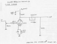
1. The linestage is based on two halves of 6DJ8/6922, in parallel to each other, probably in order to lower the (highish) output impedance.
2. Output is taken from the Anode of both triodes.
3. Plate voltage is fed by a floating regulator, based on LM723 regulator and IRF-710 Mosfet, pretty much in line with this schematic, with some changes.
4. The regulator takes 315VDC, and brings it down to 245V DC, feeding the plate of the 6922, via 12K resistors.
5. The plate voltage is about 120V, current of 5-5mA each triode.
6. The CD input, has a series resistor of 31K, so as to lower the gain.
7. The cathodes have switchable bypass cap, which may increase the gain further, from the standard 23 dB to 30dB (!!).
So I had a few objectives in mind:
1. Reduce the output impedance.
2. Reduce the background noise.
3. Reduce the gain.
First step
Reduce the regulator output from 245V to 122v. This is done with LM723 by changing the resistor between non-inverting input (pin 5) to VRef (pin 6), from 10k (original) to 20k (new).
Second step
Reduce Anode resistors from 12K to 3K, by bypassing 3 out of the 4.
Also:
1. Switch off the bypass caps (switch to "Low" position).
2. Use any input other than CD input.
Results:
1. Plate voltage is now 93VDC
2. Bias current 5mA
3. Output impedance now reduced to 3K, instead of 12K.
4. Gain is reduced to 16dB (1:6).
5. High frequencies are back !!
6. its DEAD quiet !!
Now it sounds so much better, more alive and dynamic, and much more smooth.
Note: each Mosfet (IRF-710) now drops almost 200V, which means it dissipates 2W. Make sure to leave the preamp well ventilated !
Yair
I found this thread after searching on Google.
I spent a few hours with this little gem, thinking how I can make it better.
The circuit is as simple as it gets:
1. The linestage is based on two halves of 6DJ8/6922, in parallel to each other, probably in order to lower the (highish) output impedance.
2. Output is taken from the Anode of both triodes.
3. Plate voltage is fed by a floating regulator, based on LM723 regulator and IRF-710 Mosfet, pretty much in line with this schematic, with some changes.
4. The regulator takes 315VDC, and brings it down to 245V DC, feeding the plate of the 6922, via 12K resistors.
5. The plate voltage is about 120V, current of 5-5mA each triode.
6. The CD input, has a series resistor of 31K, so as to lower the gain.
7. The cathodes have switchable bypass cap, which may increase the gain further, from the standard 23 dB to 30dB (!!).
So I had a few objectives in mind:
1. Reduce the output impedance.
2. Reduce the background noise.
3. Reduce the gain.
First step
Reduce the regulator output from 245V to 122v. This is done with LM723 by changing the resistor between non-inverting input (pin 5) to VRef (pin 6), from 10k (original) to 20k (new).
Second step
Reduce Anode resistors from 12K to 3K, by bypassing 3 out of the 4.
Also:
1. Switch off the bypass caps (switch to "Low" position).
2. Use any input other than CD input.
Results:
1. Plate voltage is now 93VDC
2. Bias current 5mA
3. Output impedance now reduced to 3K, instead of 12K.
4. Gain is reduced to 16dB (1:6).
5. High frequencies are back !!
6. its DEAD quiet !!
Now it sounds so much better, more alive and dynamic, and much more smooth.
Note: each Mosfet (IRF-710) now drops almost 200V, which means it dissipates 2W. Make sure to leave the preamp well ventilated !
Yair
Yarif, I had a couple questions regarding your description of the stock circuit. Do you mean there is a single 12K plate resistor feeding the plates in parallel? What value cathode resistor?
Thanks.
Originally, there are 4 resistors 3KOhm/1W in series, feeding both plates.
Now there is only one
")
The cathodes have 560 Ohm for each one, with switchable bypass cap of 470uF, for increasing the gain.
Cheers, Yair
Request: The schematic of Audible illusions MODULUS 3A
Hi... just want to ask, did you get the schematic of Audible illusions MODULUS 3A? because I need it as well.. it will be glad if you share it to me as well. my email is musicHunter@hotmail.com
Thanks.
Hi... just want to ask, did you get the schematic of Audible illusions MODULUS 3A? because I need it as well.. it will be glad if you share it to me as well. my email is musicHunter@hotmail.com
Thanks.
I just found this 5yo post..
Anyway I was tempted to implement a similar mod for basically the same reasons, decrease gain and the output impedance, but I have a doubt about it.
By decreasing the Ra, you necessarily increase the quiescent Ia thus increasing the bias voltage.
I guess that AI engineers selected a biasing point to achieve low distortion and if you move much higher or lower you'll see more distortion. Isn't it the case with your modification?
Also, more quiescent current = more dissipated power. Aren't you worried about reducing the tube lifespan and about pushing the PSU towards it's limits with consequent increased 60hz noise in the DC line?
Hi
I found this thread after searching on Google.
I spent a few hours with this little gem, thinking how I can make it better.
The circuit is as simple as it gets:
1. The linestage is based on two halves of 6DJ8/6922, in parallel to each other, probably in order to lower the (highish) output impedance.
2. Output is taken from the Anode of both triodes.
3. Plate voltage is fed by a floating regulator, based on LM723 regulator and IRF-710 Mosfet, pretty much in line with this schematic, with some changes.
4. The regulator takes 315VDC, and brings it down to 245V DC, feeding the plate of the 6922, via 12K resistors.
5. The plate voltage is about 120V, current of 5-5mA each triode.
6. The CD input, has a series resistor of 31K, so as to lower the gain.
7. The cathodes have switchable bypass cap, which may increase the gain further, from the standard 23 dB to 30dB (!!).
So I had a few objectives in mind:
1. Reduce the output impedance.
2. Reduce the background noise.
3. Reduce the gain.
First step
Reduce the regulator output from 245V to 122v. This is done with LM723 by changing the resistor between non-inverting input (pin 5) to VRef (pin 6), from 10k (original) to 20k (new).
Second step
Reduce Anode resistors from 12K to 3K, by bypassing 3 out of the 4.
Also:
1. Switch off the bypass caps (switch to "Low" position).
2. Use any input other than CD input.
Results:
1. Plate voltage is now 93VDC
2. Bias current 5mA
3. Output impedance now reduced to 3K, instead of 12K.
4. Gain is reduced to 16dB (1:6).
5. High frequencies are back !!
6. its DEAD quiet !!
Now it sounds so much better, more alive and dynamic, and much more smooth.
Note: each Mosfet (IRF-710) now drops almost 200V, which means it dissipates 2W. Make sure to leave the preamp well ventilated !
Yair
Could someone have the schematic circuitry of the separate modules 3 power supply, since that yesterday, it burns and smoke, seems that something short circuit, Million Thanks my email address is <redacted by moderator>I'm needing this schematic. You can send me via email:<redacted by moderator>
Thanks.
Last edited by a moderator:
- Home
- Amplifiers
- Tubes / Valves
- Request: The schematic of Audible illusions MODULUS 3