This thread is intended for newbies like me not knowing what to do with a oscilloscope. What setting on the scope and where in the circuit to probe etc etc..This is only for the JLH High Power class A circuit. No need to be too detail. Just a rough idea as to.
1/ Checking for amp stablility. How to measure and understand what the scope is telling in a simple way.
Where to safely connect the probe, illustrated on the schematic diagram of various probe points.
Establish benchmark figures and interpretation at various point in the circuit with regard to output transistors. Driver transistor etc.
2/ Checking for noise. At the PSU. At the speaker output etc.
Simple task list with the scope to get a clean bill of health for the newly assembled JLH before daily use.
All pointers and helpful hints are welcome and appreciated.
Best Regards
Hi,
Before you can undertake any measurements you have to know the 'scope is calibrated correctly. From the pics in the other thread it looked like you were getting the overshoot with a X1 lead. The 1 Khz squarewave output-- have I got that right, is that what your scope puts out at it's cal socket -- should be square on all volts/div ranges when connected with a X1 probe. If it's not - compare also with channel 2- then the attenuators inside the 'scope require adjusting. Note, unless these have been twiddled in the past they should never need touching.
When you use a X10 probe you adjust the trimmer in the probe itself to obtain a "flat" squarewave and this adjustment should be correct then for all volts/div settings on the 'scope.
The squarewave response has to be right as it will affect all other measurements.
Remember the scope shows peak to peak voltages not RMS. So in the U.K. our 240 volt mains would be 680 pk/pk on the 'scope.
DO NOT try and measure the mains by the way.
Is the volts/div accurate ? The 'scope measures DC as well as AC so get some batteries 1.5v 9 v etc, read them on a DVM then read them on the scope and check the readings agree.
Safety, The 'scope should be earthed (mains earth) at all times.
This however means the probe is also connected to mains earth. Be aware therefore that you cannot connect the ground lead of the probe to say a positive rail in an amp that is also earthed. Big bang if you try that .
.
Do you have an audio signal generator etc or a test CD with various tones on it ?
Regards Karl
Before you can undertake any measurements you have to know the 'scope is calibrated correctly. From the pics in the other thread it looked like you were getting the overshoot with a X1 lead. The 1 Khz squarewave output-- have I got that right, is that what your scope puts out at it's cal socket -- should be square on all volts/div ranges when connected with a X1 probe. If it's not - compare also with channel 2- then the attenuators inside the 'scope require adjusting. Note, unless these have been twiddled in the past they should never need touching.
When you use a X10 probe you adjust the trimmer in the probe itself to obtain a "flat" squarewave and this adjustment should be correct then for all volts/div settings on the 'scope.
The squarewave response has to be right as it will affect all other measurements.
Remember the scope shows peak to peak voltages not RMS. So in the U.K. our 240 volt mains would be 680 pk/pk on the 'scope.
DO NOT try and measure the mains by the way.
Is the volts/div accurate ? The 'scope measures DC as well as AC so get some batteries 1.5v 9 v etc, read them on a DVM then read them on the scope and check the readings agree.
Safety, The 'scope should be earthed (mains earth) at all times.
This however means the probe is also connected to mains earth. Be aware therefore that you cannot connect the ground lead of the probe to say a positive rail in an amp that is also earthed. Big bang if you try that
. Do you have an audio signal generator etc or a test CD with various tones on it ?
Regards Karl
Sand Box
Hi Karl,
When I connect the probe to the (4. Select CH1 VERTICAL MODE and insert the tip of the Channel 1 probe into the PROBE ADJUST output jack.) Cal socket I left the other clip of the probe lead not connected to anything. I assume this must be the (ground) as to the main tip of the probe be +ve am I correct?
The volts/div seems ok. It is just me not getting used to reading the scale on the screen sometimes. That is the only thing I dare to poke the probe, batteries for now")
Are you trying to set me up using a working system as my sand box for using the scope?
Sorry, I have no signal generator.
I have a test CD with different frequency on different tracks. I also have a small DVD player that can be used to play that CD.
Once the new probe delivered to me I can start check to see if it is calibrate correctly. I wanted to buy 2 probes but the guy selling on e-bay only has 1 left. I will get this one sometime next week.
So the sand box consists of all working:
1/ DVD or CD player
2/ Power amp
3/ Speaker
Let me try and setup the sand box first this weekend...
Best Regards
Hi Karl,
When I connect the probe to the (4. Select CH1 VERTICAL MODE and insert the tip of the Channel 1 probe into the PROBE ADJUST output jack.) Cal socket I left the other clip of the probe lead not connected to anything. I assume this must be the (ground) as to the main tip of the probe be +ve am I correct?
The volts/div seems ok. It is just me not getting used to reading the scale on the screen sometimes. That is the only thing I dare to poke the probe, batteries for now
Are you trying to set me up using a working system as my sand box for using the scope?
Sorry, I have no signal generator.
I have a test CD with different frequency on different tracks. I also have a small DVD player that can be used to play that CD.
Once the new probe delivered to me I can start check to see if it is calibrate correctly. I wanted to buy 2 probes but the guy selling on e-bay only has 1 left. I will get this one sometime next week.
So the sand box consists of all working:
1/ DVD or CD player
2/ Power amp
3/ Speaker
Let me try and setup the sand box first this weekend...
Best Regards
Hi,
Having a measure with your test disc is as good a place to start. Just connect the 'scope to the line out sockets on the DVD, ground lead to the line out ( phono socket ? ) outer.
Try and calculate the frequencies you see on the 'scope. This will help confirm the timebase is accurate as well. Freq = 1/T So 1 millisecond for a complete cycle on the scope screen would be 1Khz. The test disc frequencies will be absolutely accurate to fractions of a percent.
I am still confused with the probe test thing on your 'scope.
Is this a 1Khz squarewave output. If you connect the channel 1 input here can you get a squarewave on the screen ? If you can, then with a X1 lead it should be square - no over/under shoot.
Regards Karl
And whats a sandbox ? Never heard that expression before
Sandbox is the like playground for kids so to speak.
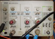
I have connected the dvd player to channel 2 with a interconnect (coax) with a RCA adaptor, see in picture in blue. The dvd player is set to play on repeat of a track that plays 1kHz square wave.
I will attach 2 pictures in the following posts.
Picture one showing the settings.
Picture two showing the result of those settings.
Attachments
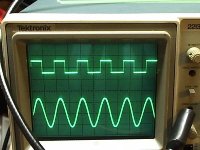
Top Display
Channel 1 the black coax is connect to the scopes own CAL output at 1kHz 500mv P-P
Bottom Display
Channel 2 is the 1kHz square wave signal from the Sheffield test CD. But it does not look square no matter what settings are those dials are at.
Do they make any sense?
I tried to attach the second picture but for some reason I keep getting the picture size is too big although it is only 42kb
Ouch chris ma,
Sounds like not only the butcher but the fryer too! Yikes!
But Fried Chicken Thighs are delicious, not sure about a Digital Camera though.
Do they warn about this in the instructions? Maybe there is a fuse. If not, hopefully it is still under warranty!
Good luck!
BTW, I am a newbie too and I am interested about this as well for when I get a scope too.
Regards//Keith
Hi,
That's a pity about the camera. Isn't USB supposed to be plug and play, I think I would have a whinge about that !
Right --- I am still confused. The picture in post 7. Where has that squarewave come from. Is it the CD or the 'scope cal output.
Just confirm what we are looking at
When making any measurements you need all the "variable" controls on the 'scope ( Any pots in other words ) in the cal or calibrate position. If this isn't done the settings on the attenuator and the timebase are meaningless.
O.K. Amplitude of the sinewave on the screen. As an example if the 'scope is set to 1V/DIV and the sinewave is 4.25 squares from tip to tip this equals 4.25 Volts peak to peak. To find the RMS value ( only for sine waves ) divide the pk/pk by 2 to get the peak value. 2.125 volts peak in this case. Then divide this by the square root of 2. So the RMS value of 4.25 V pk/pk is 1.5 volts RMS. So working the other way a C.D. player with an output of 2Vrms will show on the scope as 2*1.414 *2 which is 5.65 volts pk/pk.
Regards Karl
Edit, just had another look at your pic, it's from the 'scope cal output isn't it. That looks fine, and when you get your X10 probe you adjust the trimmer in the probe so that the tops and bottoms of that squarewave are flat. When you try it it's obvious what you do.
Hello,
Good news the camera is fine after replaced it with new batteries.
When scope is set at 1V/DIV
RMS in Volts = Number of squares (Pk-Pk) / 2 / 1.4142
1.5 = 4.25 / 2 / 1.4142
Does it matter what frequency? Or is it a normal practice that 1 kHz test frequency used in this case?
Experiment: try to find out what the C.D. players output at in RMS compare with what the manual stated in the specification section of a particular C.D. player.
1/ Reset Base Line
2/ Feed the scope with 1 kHz signal from C.D. player by connecting the probe to the audio output RCA center pin with probe ground to RCA outer jack.
3/ If the scope is set at 1V/DIV then count the number of squares peak to peak displaying on screen.
4/ use formula RMS in Volts = Number of squares (Pk-Pk) / 2 / 1.4142
Question:
a/ What if the scope is set at 2V/DIV then?
Will it become RMS in Volts = Number of squares (Pk-Pk) / 4 / 1.4142
b/ What if the scope is set at 0.5V/DIV then?
Will it become RMS in Volts = Number of squares (Pk-Pk) / 1 / 1.4142
c/ With this scope I should be able to measure from 2mV to 50V DC like any Volt meter am I correct?
Thanks a lot Karl
That's a pity about the camera. Isn't USB supposed to be plug and play, I think I would have a whinge about that !
Good news the camera is fine after replaced it with new batteries.
The squarewave is from the scopes PROBE ADJUST connector / scope cal outputRight --- I am still confused. The picture in post 7. Where has that squarewave come from. Is it the CD or the 'scope cal output.
Just confirm what we are looking at
Yes, this is what the manual suggested procedure “OBTAIN BASELINE” before use each time.When making any measurements you need all the "variable" controls on the 'scope ( Any pots in other words ) in the cal or calibrate position. If this isn't done the settings on the attenuator and the timebase are meaningless.
O.K. Amplitude of the sinewave on the screen. As an example if the 'scope is set to 1V/DIV and the sinewave is 4.25 squares from tip to tip this equals 4.25 Volts peak to peak. To find the RMS value ( only for sine waves ) divide the pk/pk by 2 to get the peak value. 2.125 volts peak in this case. Then divide this by the square root of 2. So the RMS value of 4.25 V pk/pk is 1.5 volts RMS. So working the other way a C.D. player with an output of 2Vrms will show on the scope as 2*1.414 *2 which is 5.65 volts pk/pk.
When scope is set at 1V/DIV
RMS in Volts = Number of squares (Pk-Pk) / 2 / 1.4142
1.5 = 4.25 / 2 / 1.4142
Does it matter what frequency? Or is it a normal practice that 1 kHz test frequency used in this case?
Experiment: try to find out what the C.D. players output at in RMS compare with what the manual stated in the specification section of a particular C.D. player.
1/ Reset Base Line
2/ Feed the scope with 1 kHz signal from C.D. player by connecting the probe to the audio output RCA center pin with probe ground to RCA outer jack.
3/ If the scope is set at 1V/DIV then count the number of squares peak to peak displaying on screen.
4/ use formula RMS in Volts = Number of squares (Pk-Pk) / 2 / 1.4142
Question:
a/ What if the scope is set at 2V/DIV then?
Will it become RMS in Volts = Number of squares (Pk-Pk) / 4 / 1.4142
b/ What if the scope is set at 0.5V/DIV then?
Will it become RMS in Volts = Number of squares (Pk-Pk) / 1 / 1.4142
c/ With this scope I should be able to measure from 2mV to 50V DC like any Volt meter am I correct?
It is from the cal output.Regards Karl
Edit, just had another look at your pic, it's from the 'scope cal output isn't it. That looks fine, and when you get your X10 probe you adjust the trimmer in the probe so that the tops and bottoms of that squarewave are flat. When you try it it's obvious what you do.
Thanks a lot Karl
awasson said:Chris are you sure that disk has a square wave 1k tone?
I have a number of test disks and I think they are all sine waves.
Andrew
Hi Andrew,
I am not sure, but it is the CD's cover stated that it is supposed to be same as the other track of 100 Hz square wave but at 1 kHz. I tried the 100 Hz track as well but it only shown as sine wave as well. I guess it may have been misprinted on the CD cover.
Hi,
You always read the "number of squares" as accurately as you can. If your 'scope is set on 5Mv/div and you have a signal of 3.85 squares then that is 3.85 X 5Mv or 19.25 Mv. Same goes for the timebase, at say 20microseconds/div a signal that "repeats" every 3.65 squares along the horizontal axis is 3.65 X 20E-6 or 73 microseconds. The frequency is therefore F =1/T or 1/73E-6 or 13698 Hz.
A 'scope is not as accurate as meter and is only as accurate in any case to how well you can read it.
When measuring on the horizontal axis for determining frequency pick a point on the waveform (anywhere but usually easiest where it crosses the center line) and count the number of squares untill the same point is repeated on the waveform.
For amplitude you have to stick to sine waves for converting peak to rms values. For other repetitive waveforms there are various form factors that can be applied, but stick to sine waves for now.
Regards Karl
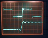
I see your back , The setting of the attenuator and timebase don't of course affect the actual reading, a signal of 4 squares at 1V/Div is 2 squares at 2V/div and so on. In either case it's still 4 volts pk/pk. Same for the timebase. A signal that repeats every 20 milliseconds will occupy 1 horizontal square at 20ms/div and 4 squares at 5 ms/div.
You asked about a 1 khz square wave from your test CD, well it just so happens I have an actual screen shot taken yesterday for another thread so I have attached it. All CD players will reproduce this identically.
, The setting of the attenuator and timebase don't of course affect the actual reading, a signal of 4 squares at 1V/Div is 2 squares at 2V/div and so on. In either case it's still 4 volts pk/pk. Same for the timebase. A signal that repeats every 20 milliseconds will occupy 1 horizontal square at 20ms/div and 4 squares at 5 ms/div. You asked about a 1 khz square wave from your test CD, well it just so happens I have an actual screen shot taken yesterday for another thread so I have attached it. All CD players will reproduce this identically.
Attachments
- Status
- This old topic is closed. If you want to reopen this topic, contact a moderator using the "Report Post" button.
- Home
- General Interest
- Everything Else
- How to measure JLH Class A with a Scope