I have just finished a pre-amp kit based around Lite audio A-15 board and MV-01 switching relay board, both obtained from DIYclub.biz.
I tried to pair it with my gainclone based on the BrianGT kit (gain 33) but on my disappointment I realized that the pre-amp gain is far too high. I could not turn the pot (100K alps) more then a degree or two without pushing 3886s into clipping.
The first question is regarding the pre-amp configuration. I wanted to have the A-15 board after the pot so it can act as a signal buffer. Is that a good idea or should I put it before the pot.
My second question regarding the pre-amp gain. I attached the schematics of the preamp (one channel only) and the accompanied regulated power supply board. Does anyone have an idea how to cut down the pre-amp gain.
I have quite sufficient gain out of the power amp - I need pre-amp only as a "signal conditioner" and impedance matching unit.
Attachments
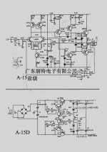
It looks like the gain of the preamp is controlled by R117. Raising the value of that resistor should lower the gain of the preamp, but like AndrewT said, reducing the gain may or may not have adverse effects on the performance of the preamp.
That said, your schematic shows a pretty classic approach to a BJT amplifier, and I *think* you should be ok with putting the gain somewhere in the 2-4 range. That corresponds to a value of R117 from 200k-400k.
That said, your schematic shows a pretty classic approach to a BJT amplifier, and I *think* you should be ok with putting the gain somewhere in the 2-4 range. That corresponds to a value of R117 from 200k-400k.
You have four options: change the gain of the preamp, change the gain of the power amp, change the gain of both, or insert a voltage divider somewhere in the signal path. The gain of that preamp should be equal to (1+R120/R121), so you can change either or both of the resistors to change the gain but you may encounter stability issues as Andrew mentioned. The gain of the amp is set in a similar manner. The safest option would be to insert a voltage divider somewhere in the signal path, either before the preamp or between the preamp and the power amp.
Thanks guys heaps.
I have to repeat my first question - if someone can comment - am I better off with the current configuration (pre-amp after the pot to act as a buffer) or pre-amp before the board (then I am having problems of 100K pot looking at 25K input at the gainclone.
Also - regairding voltage divider - is that just a T resistor network that acts as an attenuator - say 10K in the line and 5K between the line and the ground would give me 9.55dB attenuation - A=20*log(R2/(R1+R2)).
And finally - more regarding the impedance matching. It is not super easy for me to change anything on the gainclone side but I can easily modify the pre-amp board. Should I change anything to better match output and input impedances. At this stage I am measuring ~11kohm at the output of the pre-amp but that is only the resistive component. Should I be bothered with this at all considering 25kohm at the gainclone input.
..and one more - is there any real benefit in having this preamp board if I have to eat all the gain with resistors. This is more in the big picture by taking into account impedance matching issue (pre-amp as a buffer), or this extra transistors are just adding noise to the base signal.
Uf too many questions - sorry guys
Some of the amplifier gain settings that I've tested result that you can use 1k at the NFB instead of the stock 680R.
Just take the 1k off the input and recycle it over to the NFB.
That way, you can also change your input in-series resistor to 2.2k.
That adjustment will cut your amp gain a bit, and I think it sounds nice that way.
Problem: A 100k pot usually has a fairly low resolution when its nearly all the way down. Solution: Just swap it out for a voltage divider, also called "fixed l-pad" which is just 2 resistors per channel. Chances are good that a 50k here will be more quiet than a 100k. In that case, the sum of the 2 resistors (per channel) will equal (or almost equal) 50k. Its my best guess.
Anyway, a resistor is usually higher resolution than a pot.
A voltage divider looks like
ground
ground source
______V
____load
Usually, you just read off the pot's preferred settings with a multimeter and then replace it with the same value resistors doing the same job in the same way.
(To change from 100k to 50k, just use half values).
If I were in your shoes I would try changing the gains of the pre and power amps. For the preamp I would change R120 from 10kohm to around 5kohm. That will bring the gain down to around 6V/V. For the power amp I would change R3 from 680ohms to around 1.1kohm (while leaving R1 in place), which will bring the gain down around 21V/V. That will lower the total gain of your system from about 363V/V (51dB) to around 126V/V (42dB). That's still rather high but should allow you to change the volume pot setting a bit more.
That is exactly what I was planning to do. Also I will have voltage divider as a backup option.
However I am still a bit puzzled with the impedance matching issue.
I am correcting myself - what I was planning on the preamp side is to go down to gain 3 by replacing R121 from 1K to 5K.
Thinking loudly - this preamp could be quite a nice headphone amp as well.
However I am still a bit puzzled with the impedance matching issue.
I am correcting myself - what I was planning on the preamp side is to go down to gain 3 by replacing R121 from 1K to 5K.
Thinking loudly - this preamp could be quite a nice headphone amp as well.
I tend to agree with you. But I am always for buffering the pot from the power amp input somehow. Might try with a MF X buffer stage or simmilar.
Considering the gain of this preamp - to continue thinking loudly - I might try it as a headphone amp (might not have enough gain for my HD600s) and use the passive preamp - relays + 100K pot.
I know that 100 K pot is a bit excessive but I might try - it wont hurt (a lot") )
)
Considering the gain of this preamp - to continue thinking loudly - I might try it as a headphone amp (might not have enough gain for my HD600s) and use the passive preamp - relays + 100K pot.
I know that 100 K pot is a bit excessive but I might try - it wont hurt (a lot
)Hi,
I too like the buffering idea to ensure minimum source impedance before the cables into the next stage.
But a buffer in this context can be a unity gain buffer.
If you cannot advance your volume pot off the stop without getting overload, then a little 10db of reduced gain is not going to solve your tiny volume control adjustment problem.
And yes, that preamp looks a though it might be worth using as a high impedance headphone amp.
I am perplexed as too why the front end uses lm394 as a line stage amplifier. This is more indicative of an amplifier for very low signal levels. Could it be the stage that follows a passive RIAA?
That sounds like an admission of lack of research.decky said:You are probably right -
You mean on my side - well my knowledge is not that great - but learning is always fun. Now I know better.
I guess I was too optimistic and wrongly assuming that everyone makes pre-amps with gains of up to 6dB or as unity buffers. I was obviously wrong. I recently heard a very nice valve pre-amp with a gain of over 30dB. Although paying almost 3K my friend had to sell it since it was over-loading the rest of the system (even with 10dB attenuation).
My lack of knowledge costed me only $50
that is correct.assuming that everyone makes pre-amps with gains of up to 6dB or as unity buffers
It's your high gain that is the problem, but not a write off if you can use it for headphones.
Have you tried turning down the amp gain like BWRX and I both mentioned? Okay, its really weird that he and I agreed on something, especially the same gain setting. I'll recover from the surprise some day. Anyway, that adjustment will make the amp a little deaf. So unless your headphone amp is powerful enough to smoke the headphones. . .
Hey, it seems like it is too. You might want to ask the headphone amp designer what they recommend (from their experience) as an optimal approach to avoid headphone damage?
Clipping. . . I wonder if the chip amp is clipping while breaking the drywall and shaking the pictures off the walls. . . or if its clipping because its eating DC at the input and/or has too little voltage at the supply and/or has a ground loop?
I'll recover from the surprise some day. Anyway, that adjustment will make the amp a little deaf. So unless your headphone amp is powerful enough to smoke the headphones. . . Hey, it seems like it is too. You might want to ask the headphone amp designer what they recommend (from their experience) as an optimal approach to avoid headphone damage?
Clipping. . . I wonder if the chip amp is clipping while breaking the drywall and shaking the pictures off the walls. . . or if its clipping because its eating DC at the input and/or has too little voltage at the supply and/or has a ground loop?
- Status
- This old topic is closed. If you want to reopen this topic, contact a moderator using the "Report Post" button.
- Home
- Amplifiers
- Chip Amps
- Pre- amp gain and LM3886