I am wanting to power 7 12ax7 tubes with DC (they are going on a PCB that has traces for the heater supply) with a transformer that only has 6.3VAC CT. I was thinking of using a simple PI filter so that the DC voltage will be kept high.
How do I calculate the values I use for the PI filter?
I tried using the duncan power supply designer, but I am unsure of the resistance of the load.
thanks
d1
How do I calculate the values I use for the PI filter?
I tried using the duncan power supply designer, but I am unsure of the resistance of the load.
thanks
d1
You can can switch the load to a constant current one in Duncans.
You may have trouble getting the output you want due to transformer, diode and filtering losses. Even with Schottky diodes.
Consider using AC to heat the tubes, and giving the heaters elevated DC reference to reduce noise.
You may have trouble getting the output you want due to transformer, diode and filtering losses. Even with Schottky diodes.
Consider using AC to heat the tubes, and giving the heaters elevated DC reference to reduce noise.
thanks for the quick reply. On a turret board prototype, I am using elevated heaters, and it is working well. However I found on previous experiments with heater traces on the PCB I was still getting hum in sensitive sections.
One option is for me to put the 6.3VAC winding in series with the unused 5V winding for the rectifier. I suppose I could use the connection between the windings for the centre tap. I could then regulate this down to get the value I need.
comments?
One option is for me to put the 6.3VAC winding in series with the unused 5V winding for the rectifier. I suppose I could use the connection between the windings for the centre tap. I could then regulate this down to get the value I need.
comments?
I suppose a PCB does make twisting heater leads a bit problematic.
Putting the windings in series should work. Be sure the transformer is rated for much more current than your load (at least 5/3 more), capacitor input DC is much more strain than AC. It would also make LC input feasible, which does not have this issue and has other benefits, though it might be overkill here.
Schottky diodes are preferred.
You can make an artificial center tap with a pair of 100 ohm resistors connecting across the heater to CT. I think this is preferable to a not center tap of two dissimilar windings.
Floating the heater is still beneficial with DC heaters.
d1,
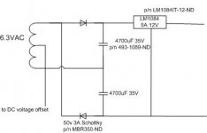
Can you set the PCB up so the 'X7 heaters run at 12 V.? Regulated 12 VDC supplies are easy enough to build and the reduced current demand HELPS.
The 6.3 VAC winding has to be rated at 4X the DC heater draw, which in this case is 1.05 A. "Full wave" voltage double the 6.3 VAC using a pair of Schottky diodes into a stacked pair of LARGE value 'lytics. Follow the doubler stack with a 3 A. adjustable linear regulator. Heat sink the IC well.
BTW, whenever you cap. I/P filter, count on being able to use only 1/2 the rectifier winding's VA capability. It's a matter of I2R heating in the trafo.
About the floating vs connecting the CT to a DC offset. Why?
Biasing a heater supply off of B+ is done for 2 reasons. It prevents exceeding the max. allowable heater to cathode potential. The technique can be crucial in a DC coupled design, which employs both sections of a twin triode. The 2nd reason is noise control. Making the heater + with respect to the cathode keeps thermionic electrons emitted by the heater from flowing to the cathode. When heaters are AC energized, thermionic flow to the cathode can increase residual hum.
Neither of the above considerations applies (AFAIK) in your preamp, when the 'X7 heaters are energized with DC. Also, biasing a winding which is rectified might cause a malfunction.
- Status
- This old topic is closed. If you want to reopen this topic, contact a moderator using the "Report Post" button.
- Home
- Amplifiers
- Tubes / Valves
- Simple DC Heater Supply