I assume that a passive crossover was used when you did the testing you include with your post. If so, then I suggest using a series notch filter, wired in parallel, added after the crossover network. This places the notch filter between the crossover and the woofer.
Tune the notch filter for 2 kHz. Since you are already down about 35 dB, I don't believe that you will have to worry much about the series resistor value in the notch filter. You can tweak it if you want, but it should have little audible impact.
I should say, however, that I do not trust the accuracy of your published graphs. Looks too good. I have to assume that actual performance is far worse than what you show here. That is too bad. It makes it very difficult for anyone else to help you when you provide bad data.
Best of luck to you with your project.
Mark
Mark, Thank you for your input. What you describe is perhaps the circuit I may use, and somewhere I read about tuning notches to 2kHz..........However, I don't have any frame of reference as to how to determine the component parts.....I have read Dickasons writing on notches but when I applyed his math in my simulator, there was no change on the resultant curve.............So, would you possibly share with me how I may determine component parts values accurately?.........In reference to my graphs: I used Jeff Bagbys' Crossover Designer 5.1 along with the FRD tools found at rjbaudio.com ..............I will take your statement that my graph Looks too good, as a compliment..........Thank You.........As far as the actual performance of the speaker goes: You would be shocked to say the least..........They perform very nicely. A great deal of time went into the design, using the tools I mentioned, along with the help from some friends I have made on this forum............They do suffer, however, from a slight soundstage imbalance, which I believe can be remedied. The notch I seek to install is just the first of a few tweaks I am gonna perform.........So by trusting my data, and my ears, I seek the experience of people like you, who have the knowledge and skills, in the hope that I may accomplish this.............Respectfully........Omni
Cal.........Here are the specifics: Rise begins at 1500 Hz.....up to 1882 Hz............So frequency extremes of notch would be 1500-1882 or somewhere 2000?..................Impedance of driver at 1500Hz is 17ohms...........Impedance at 1882 Hz is 19.7 ohms.........attenuation in the neighborhood of 8 db............I hope this information is adequate for our purposes............If not, please let me know.............Respectfully.............Omni
omni,
I think what MarkMcK was saying about your graphs - is they look like smoothed data. Real world frequency response (before someone smooths it) shows a lot more peaks / dips. Therefore, to accurately pinpoint a frequency anomaly and correct it, you need to work on the raw response.
Although - a smoothed response should show a general imbalance, the exact frequency a notch should target would be confirmed looking at the raw response.
Cheers,
David.
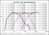
Omni, you say you want a notch from 1500 - 1899 hz, which means you want to attack the bump on the summed curve - its a narrow notch, and you cannot do that without real measurements
You can attack the individual slopes much better with broad notches
Your "small" woofer problem range from 800 - 3000hz, which means through the whole midrange, or at least from 1500 - 3000hz, and it correlates very well with what you actually hear when listening
The reason of this woofer unsteadiness might happen because the paralel cap "gives up" at some point -that is why I use another inductor, which would give 18db, but thats not really needed nor wanted, hence the "bypassed attenuation"
Attachments

Tinitus, I now see what you are saying.........I was considering the individual woofer slope as you mention, however, only in the narrow zone of those spikes. So are you saying that we need to develope a notch for the frequencies of 800 to 3000?..............DaveBullet......This response curve is a curve that was created based on my modelling of the crossover using Jeff Bagbys Crossover Designer with FRD and ZMA files that were created in the Frequency Response Tools at rjbaudio.com Traces were made of the manufacturer response curves then processed through a series of programs to produce the Response files used in the crossover simulator. I hear what you are saying, and will continue to pursue this problem with the resources available to me..............I have no measuring equipment, so I have to go by the graph, and by ear, and by the help from people like you on this forum.................Cal, I see you have been steadfastly working on my problem, and I am extremely grateful...........See Tinitus' post...I may have given you an uneducated set of facts? By the way, Cal when I modelled some notches and it really lowered my woofer impedance to what I may consider dangerous levels, so perhaps Tinitus' information on the broad notch is the direction to go?.................Respectfully...................Omni
- Status
- This old topic is closed. If you want to reopen this topic, contact a moderator using the "Report Post" button.
- Home
- Loudspeakers
- Multi-Way
- notch filter help