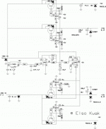
Hello All,
I currently have a Jung Regulator PCB made by AOS. Is it possible to modify it to output 5V without significantly altering the board? In the schematic (here: http://www.aoselectronics.com/gfx/jsr/jung_pos.gif), you can see that the reference voltage is 6.9V, so that clearly would have to be dropped below 5V for a 5V output. Any ideas?
Thanks,
Bryan
bryman79 said:Hello All,
I currently have a Jung Regulator PCB made by AOS. Is it possible to modify it to output 5V without significantly altering the board? In the schematic (here: http://www.aoselectronics.com/gfx/jsr/jung_pos.gif), you can see that the reference voltage is 6.9V, so that clearly would have to be dropped below 5V for a 5V output. Any ideas?
Thanks,
Bryan
Other reference?
I've since run across ALW's pdf article that suggests using the LM336Z-2.5 and the AD817. I've emailed him, but no response. As such, I have two questions:
1. Why the change from AD825 to AD817? I've heard that both will operate at voltages below 5V...
2. Anyone have experience (listening or measuring) with the LM336Z-2.5 vs. the LM385-2.5?
Thanks,
Bryan
1. Why the change from AD825 to AD817? I've heard that both will operate at voltages below 5V...
2. Anyone have experience (listening or measuring) with the LM336Z-2.5 vs. the LM385-2.5?
Thanks,
Bryan
peranders said:+- 20 V unstabilized voltage on OP07? A bit tough, don't you think?
Absolute maximum rating: +/-22V according to datasheet!
No failure in 3 years!
Okay, so I got the regulator to output 5V. Thanks moamps for the link... I didn't realize the U3 diode needed to be changed. Since I didn't have a 2.2V-2.7V zener, I improvised with a green LED instead. Would I see improved performance by using another diode in this position? Any suggestions?
Thanks,
Bryan
Thanks,
Bryan
bryman79 said:...I improvised with a green LED instead. Would I see improved performance by using another diode in this position? Any suggestions?
A green LED is just fine.
Regards,
Milan
- Status
- This old topic is closed. If you want to reopen this topic, contact a moderator using the "Report Post" button.
- Home
- Amplifiers
- Power Supplies
- Modifying Jung Regulator For 5V Output
