I must admit, these guys make some pretty impressive gear.
http://www.alab-pro.com/
Although the way they specify SMPS power output is somewhat unorthodox, I admire their bold embracing of switching power technologies for audio amplification.
They describe an audio amplifier operating mode where the supply rails are modulated to always be just a few volts above the peak program waveform.
(class H -continuously variable, or H/CC)
Alab-Pro SMPS for power amps - Class "TD2" concept
This begs the question:
Is a power amplifier's gain dependent on supply voltage to any extent? PSRR data for power ampifiers is not always available, but I am willing to speculate it might be lower than the PSRR of integrated op-amps.
If you took a typical op-amp's PSRR or 100dB and assumed that figure for a power amp, that would suggest a harmonic distortion
penalty of 0.001% added by the supply rail modulation technique.
Most of us could live with that figure, however, a Power Amp's PSRR may be lower than 100db, by how much, I don't know.
Nevertheless, it is useful to contemplate such a supply rail modulation in any power amp design that uses an SMPS.
It is certainly within the transient response capabilities of any voltage-mode SMPS feedback loop to respond to changing audio signals. I would in fact suspect that audio frequency transients above 1 KHz would not even need to be followed cycle-by cycle, but followed at a lower-frequency envelope instead.
I would want a voltage-mode controlled SMPS in this case, to better track the secondary side, while latting a preregulator PFC stage take care of line regulation.
I like PFC stages, not because it makes regulatory agencies happy --I frankly couldn't care less-- but because in smoothing the line voltage, they reduce the size of electrolytic bulk caps required, with all their limited lifetime conundrums.
Comments, anyone?
Andy
PSSR, I guess would generally be lower than the gain of the amp. For a class A amp, there could be some cross-cancellation, though.
Dynamically regulating the voltage from the secondary filter caps would eliminate the slow response of an optocoupler. The frequency of the tracking could be much higher, then.
I have done an LTspice simulation of a simple tracking supply which regulates from the primary side. Let me know if you are interested.
Yes subwo1, I would be interested in that primary-side tracking regulation.
Do you think optocouples would not be fast enough to track a audio signal?
There are some O/C made by Fairchild --HCPL4502--(I'm sure there may be others) that have 1MHz bandwidth.
But is it really necessary to track high frequency audio signals cycle-by-cycle, especially since they are typically much lower in amplitude than low frequencies? What if you tracked an envelope above the peaks instead? I'm betting the efficiency savings would not be much different than if you force the supply rail to dip down to zero in-between the cycle excursions. Turning one rail off while the audio program is making an excursion in the opposite rail saves no power since it happens during a time of zero current draw anyways.
So an optocoupler may not need to have a frequency response over 50 KHz or so to do well in this application.
Secondary regulation doesn't seem appealing, since I'd want all my regulation in the swich mode, and once I'm on the secondary side, I'm done switching.
Only one conundrum:
You can't use large filter caps on the supply rails any more.
They must be just large enough to filter the switching frequency, and leave alone any ripple below 2 KHz. That places the entire burden of load regulation on the switcher, and requires that the switcher not do any line regulation, since that would bring it's response below 2KHz. That kind of rules out current mode control.
All line regulation must be done in a PFC, and switching frequencies kept above 100 KHZ.
I think it's doable
Andy
The HCPL4502 is like the 6N137, but with a minimum rated CTR of 17% instead of 7%. Both still have a maximum rating of 50%. They should be able to enable a frequency response for the tracking supply which encompasses the audio band.
Sounds right. The output transistors have to be rated for the whole rail to rail voltage this way. The tracking circuitry is much more complex, too.
The tracking switcher needs to be able to continuously output the peak power of the amp because the secondary filter capacitors are small. However, if the SMPS is overload protected, it also protects the amplifier.
I have not done much work with PFC since for my projects, passively using inductors for partial correction has been simpler and more efficient.
I tried out a different compression program than the one built into Windows XP and it wiped out the built-in file compression software. I will try to make the circuit available still.
But is it really necessary to track high frequency audio signals cycle-by-cycle, especially since they are typically much lower in amplitude than low frequencies? What if you tracked an envelope above the peaks instead? I'm betting the efficiency savings would not be much different than if you force the supply rail to dip down to zero in-between the cycle excursions. Turning one rail off while the audio program is making an excursion in the opposite rail saves no power since it happens during a time of zero current draw anyways.
Sounds right. The output transistors have to be rated for the whole rail to rail voltage this way. The tracking circuitry is much more complex, too.
Secondary regulation doesn't seem appealing, since I'd want all my regulation in the swich mode, and once I'm on the secondary side, I'm done switching.
Only one conundrum:
You can't use large filter caps on the supply rails any more.
They must be just large enough to filter the switching frequency, and leave alone any ripple below 2 KHz. That places the entire burden of load regulation on the switcher, and requires that the switcher not do any line regulation, since that would bring it's response below 2KHz. That kind of rules out current mode control.
The tracking switcher needs to be able to continuously output the peak power of the amp because the secondary filter capacitors are small. However, if the SMPS is overload protected, it also protects the amplifier.
I have not done much work with PFC since for my projects, passively using inductors for partial correction has been simpler and more efficient.
I tried out a different compression program than the one built into Windows XP and it wiped out the built-in file compression software.
I will try to make the circuit available still.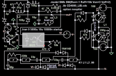
Thanks for the diagram
I'm not sure what you mean by the tracking circuit being more complex. The error signal just needs to be frequency compensated to respond well below 2 KHz and roll off above that.
And as for the output devices, they'd be rated for rail-to-rail voltage in an existing design anyways.
The intention is not to lower the output transistor ratings. It is to enable you to build a high power, low distortion class B amp, without turning it into a space heater.
Depending on how well this modulating SMPS is implemented, it could reach efficiencies very close to class D. ( possibly perturbing the relevance of the whole class D movement ).
).
The advantages of this is that it requires no modifications to the class B /AB amplifier, and can be re-fitted to existing designs. It suddenly removes the greatest single drawback of class B that made people look at alernatives in the first place.
It also makes possible class B amps that are slim, sleek, and light.
And yes, one more advantage :
:
It reduces BJT thermal runaway concerns, by lowering their temperature, and pushing their operating point deeper inside the SOAR curve, increasing reliability.
Andy
Sounds right. The output transistors have to be rated for the whole rail to rail voltage this way. The tracking circuitry is much more complex, too.
I'm not sure what you mean by the tracking circuit being more complex. The error signal just needs to be frequency compensated to respond well below 2 KHz and roll off above that.
And as for the output devices, they'd be rated for rail-to-rail voltage in an existing design anyways.
The intention is not to lower the output transistor ratings. It is to enable you to build a high power, low distortion class B amp, without turning it into a space heater.
Depending on how well this modulating SMPS is implemented, it could reach efficiencies very close to class D. ( possibly perturbing the relevance of the whole class D movement
).The advantages of this is that it requires no modifications to the class B /AB amplifier, and can be re-fitted to existing designs. It suddenly removes the greatest single drawback of class B that made people look at alernatives in the first place.
It also makes possible class B amps that are slim, sleek, and light.
And yes, one more advantage
:It reduces BJT thermal runaway concerns, by lowering their temperature, and pushing their operating point deeper inside the SOAR curve, increasing reliability.
Andy
You're welcome. Thanks.
I was considering the way the simulated circuit powering a simple resistive and inductive load would work instead of the realistic, more complex one consisting of a linear amplifier driving a speaker. Using the original circuit with a 20khz signal resulted in poor tracking because of the slow response. It now seems to do better after I removed the modulated voltage source drive from the tracking feedback and replaced it with a modulated current source between the tracking power output and the load. Now the LTspice circuit should better represent the real life circuit.
Now I have zip capability again. I hope this zip file will decompress OK.
I'm not sure what you mean by the tracking circuit being more complex. The error signal just needs to be frequency compensated to respond well below 2 KHz and roll off above that.
I was considering the way the simulated circuit powering a simple resistive and inductive load would work instead of the realistic, more complex one consisting of a linear amplifier driving a speaker. Using the original circuit with a 20khz signal resulted in poor tracking because of the slow response. It now seems to do better after I removed the modulated voltage source drive from the tracking feedback and replaced it with a modulated current source between the tracking power output and the load. Now the LTspice circuit should better represent the real life circuit.
Now I have zip capability again. I hope this zip file will decompress OK.
Attachments
WTF???? check this:
http://www.alab-pro.com/index.php?lay=show&ac=article&Id=172730&Ntype=6
Do you mean to tell me that I can buy a smps from these Alab people that puts out 4,200W continuous for the bargain basement price of $235USD? Is this for real? Who cares about their class-whatever, start buyin' up powersupplies and move 'em through e-bay$$$$$$$$$$$$$$$$$$$$$$$$
Truth is right here....
Hi EVERYONE,
The Guys from ALAB PRO are nothing but Damn...Cheaters.....only masters in cheating big companies......products and copying them
They Copy QSC PLX & PL series amps each & every single thing...
Also These So called engineers copy also LabGruppen ... Class-TD is actually from it...
They also carry same "POWERWAVE" trademark...on their amps as well...
Compare PL series of amps from QSC with them...
http://www.qscaudio.com/products/amps/powerlight2/powerlight2.htm
What QSC says about this :
http://www.qscaudio.com/cgi-bin/ultimatebb.cgi?ubb=get_topic;f=8;t=000017;p=1#000002
Duplicate product
http://www.alab-pro.com/index.php?lay=show&ac=article&Id=204921&Ntype=1
LabGruppen Original Amp:
http://www.labgruppen.com/Default.asp?Id=6595
Duplicate product...
http://www.alab-pro.com/index.php?lay=show&ac=article&Id=150237&Ntype=1
See the Truth with your eyes...how these R*A*S*C*A*L*S do their job so nicely....
Their products donot impress me, but hurts their orignal manufacturers alot....
Truth Investigated by K a n w a r
vectorplane said:I must admit, these guys make some pretty impressive gear.
http://www.alab-pro.com/
Although the way they specify SMPS power output is somewhat unorthodox, I admire their bold embracing of switching power technologies for audio amplification.
They describe an audio amplifier operating mode where the supply rails are modulated to always be just a few volts above the peak program waveform.
(class H -continuously variable, or H/CC)
Alab-Pro SMPS for power amps - Class "TD2" concept
Andy
Hi EVERYONE,
The Guys from ALAB PRO are nothing but Damn...Cheaters.....only masters in cheating big companies......products and copying them
They Copy QSC PLX & PL series amps each & every single thing...
Also These So called engineers copy also LabGruppen ... Class-TD is actually from it...
They also carry same "POWERWAVE" trademark...on their amps as well...
Compare PL series of amps from QSC with them...
http://www.qscaudio.com/products/amps/powerlight2/powerlight2.htm
What QSC says about this :
http://www.qscaudio.com/cgi-bin/ultimatebb.cgi?ubb=get_topic;f=8;t=000017;p=1#000002
Duplicate product
http://www.alab-pro.com/index.php?lay=show&ac=article&Id=204921&Ntype=1
LabGruppen Original Amp:
http://www.labgruppen.com/Default.asp?Id=6595
Duplicate product...
http://www.alab-pro.com/index.php?lay=show&ac=article&Id=150237&Ntype=1
See the Truth with your eyes...how these R*A*S*C*A*L*S do their job so nicely....
Their products donot impress me, but hurts their orignal manufacturers alot....
Truth Investigated by K a n w a r
Thank you, workhorse
for your vigilent research in finding out what the ALAB amps were actually a copy OF.
My original post was really not about amplifiers, but power supplies. I already have the amp and am looking for a more efficient way of powering it.
Apparently, the websites of QSC and LabGruppen do not reveal anything about their power supplies, to enable me to learn something, and try to duplicate them.
Furthermore, QSC and LabGruppen do not market SMPS 's to the consummer, so it's rather difficult to state whether the Alab SMPS's are faithful replicas of their branded homologues or not.
I personally hope they are, since that would give me greater confidence in using the "voltage modulating" concept, if I knew it came from a higher authority than Alab.
In any case, I don't intend to buy either product, since they BOTH are above my budget. I want to build the SMPS myself and if it means copying Alab or copying QSC in my design, I frankly couldn't care less.
This is after all a DIY forum, where people want to build stuff, rather than buy it.
Quite honestly, I would not have been able to start programming at age 14, if it hadn't been for a p*rated copy of M*crosoft C Compiler, so "cheaters" around the world have put a lot of affordable functionality into the hands of people like me. And I always stayed away from brands like Apple and Palm, who ferrociously and jealously guard their tech to keep prices high, while the rest of the world enjoyed competitive pricing and upgreadable products. Where are Apple and Palm now? Natural selection speaks.
Although I want to identify and correctly qualify a copy from the original (for which I thank you, workhorse), I hold no allegiance for the brand, nor any stock in their company.
I judge the parties strictly for what they bring ME: information. Alab has revealed a principle of SMPS operation that the brands did not, thereby enlightening me to something I want to try.
In every tech field, you find hackers who take apart equipment, and disseminate information on what they found inside. Of course, by also copying the cosmetics of the brands, and selling the copy for a profit, Alab has crossed the line between a hacker and a crook.
But take heart, I don't intend to buy anything...
Andy
Eva, please help me understand this:
If this supply tracks the audio waveform, it may need to swing an output rail from 10V to 60V in 100uS to keep up with program material. Having larger filter components on the rails would cripple this transient response. This SMPS has to walk a fine line between filtering the switching frequency (maybe 100KHz ??) and not filtering anything below 20KHz. No other common SMPS needs to do this (which also prohibits large bulk caps on the rails).
This is no ordinary power supply. You don't buy this to power a microcontroller or a welding outfit. I'm not sure the SMPS industry even has a standard for how to specify power in such a situation.
(although Alab could have been clearer on how exactly their PSU's are supplying their power, and about their unsuitability for anything autside of audio)
Andy
Don't get fooled, these power ratings are maximum peak, not continuous. Also, output inductors are tiny so output HF ripple is going to be 0.5V p-p or more...
If this supply tracks the audio waveform, it may need to swing an output rail from 10V to 60V in 100uS to keep up with program material. Having larger filter components on the rails would cripple this transient response. This SMPS has to walk a fine line between filtering the switching frequency (maybe 100KHz ??) and not filtering anything below 20KHz. No other common SMPS needs to do this (which also prohibits large bulk caps on the rails).
This is no ordinary power supply. You don't buy this to power a microcontroller or a welding outfit. I'm not sure the SMPS industry even has a standard for how to specify power in such a situation.
(although Alab could have been clearer on how exactly their PSU's are supplying their power, and about their unsuitability for anything autside of audio)
Andy
These power supplies (the ones advertised and from the pictures) doesn't track anything, and I feel they are quite rudimentary. The author may be currently developing some kind of tracking PSU or better SMPS, but this new work is not shown (altough it's vaguely advertised).
Thanks Eva, for making me re-read carefully the Alab descriptions.
OK, looks like the Alab stuff is a vicious play on words
They lift entire paragraphs of text right from the Brand name manufacturers literature.
They mention a lot of technical concepts, and let the user assume their products incorporate these concepts, but they stop just short of actually stating that their products do incorporate them.
They create a lot of B.S. names like Powerwave2, CCA, MLC, TD-Tech, all of which are lifted from the European Amp manufacturers, and yet they never clearly state that their Amps or SMPS's have this technology.
They discuss TD-Tech being an audio-tracking supply, but their stuff doesn't have TD-Tech, it has TD-2, which they don't actually describe.
There is absolutely no guarantee that their circuitry is a copy of the originals, or that it bears any resemblence to the originals. They may have just copied the faceplate, and put cr*p inside, for all we know.
(OK if Alab were buying ad space in this forum, I might get thrown in Texas for saying this, but they're not doing so right now...)
Andy
OK, looks like the Alab stuff is a vicious play on words
They lift entire paragraphs of text right from the Brand name manufacturers literature.
They mention a lot of technical concepts, and let the user assume their products incorporate these concepts, but they stop just short of actually stating that their products do incorporate them.
They create a lot of B.S. names like Powerwave2, CCA, MLC, TD-Tech, all of which are lifted from the European Amp manufacturers, and yet they never clearly state that their Amps or SMPS's have this technology.
They discuss TD-Tech being an audio-tracking supply, but their stuff doesn't have TD-Tech, it has TD-2, which they don't actually describe.
There is absolutely no guarantee that their circuitry is a copy of the originals, or that it bears any resemblence to the originals. They may have just copied the faceplate, and put cr*p inside, for all we know.
(OK if Alab were buying ad space in this forum, I might get thrown in Texas for saying this, but they're not doing so right now
...)Andy
Hi Vector....
The SMPS is Ditto copy of QSC even the PCB's are copied well....and also sold seperately....
If you want to copy than you want a schematic of Powerwave SMPS ...here it is....
visit this link...
PLX-series
http://www.qscaudio.com/support/library/schems/plx3402.pdf
PL-series..
http://www.qscaudio.com/support/library/schems/pl40.pdf
Here is Photo of PCB from QSC...
http://us.st11.yimg.com/store1.yimg.com/I/qsc_1876_1703163
Patent of Powerwave Quasi-Resonant Switching Supply of QSC..
http://patft.uspto.gov/netacgi/nph-...&l=50&d=ptxt&S1=QSC.ASNM.&OS=AN/QSC&RS=AN/QSC
For circuit Images...
http://patimg1.uspto.gov/.piw?Docid...ageNum=&Rtype=&SectionNum=&idkey=4EE14A23BFAC
Anything more ask me again....
K a n w a r
Thanks for the links, workhorse.
A real eye-opener.
They use constant voltage SMPS, then they modulate voltage to the output devices with buck MOSFET stages in the amp.
I was thinking this was a duplicate waste of heat --you lose efficiency in the SMPS, then again in the buck converter. It should be possible to do everything in one switcher.
But simulation suggests the needed transient response is difficult to achieve in one switcher.
To keep the supply 5V above the signal AND get response to 20KHz, he switching frequency would have to be over 2MHz, if you regulate using a feedback loop. Some form of feed-forward method would be needed, that predicts where the audio signal will be before it gets there (based on slope).
Either that or stick with the low frequencies.
Yes, thanks for the links workhorse!
Very enlightening indeed. I have done some experimentation on a single stage tracking supply myself and there was no way I could get it to slew higher frequencies reliably. Having a 2 stage supply with buck converters as second stage on each rail seems like a better solution. Tracking is done by comparing output of amplifier with audio input in a self-oscillatin way. There is a paper about this in the Audio Engineering Society somewhere.
Yamaha has a thing called the EEEngine on some of thier power amps that tracks. I've looked at it and it works really nicely up to above 40kHz. In thier case, it uses a conventional toroidal supply and then buck stages on each rail to track the envelope of both channels. In addition, they develped some sort of method to slew the buck outputs very quickly when needed.
http://www.yamahaproaudio.com/reviews/special/eeengine/
Good topic!
Thanks for sharing, carvinguy.
So THAT's where their pretty pictures come from!. Wow, the Alab guys lifted the entire Class H page right out of Yamaha!
They really didn't do a single thing themselves in their website.
Looks like Yamaha is doing a lot of intricate processing to track the audio, and throwing in the silicon by the shovel. As I suspected it's not a simple task.
This is what we're up against:
Worst case-- assume a 20KHz signal that rises from zero to the rail (60V) in the first cycle. That's 60V in 12.5 uSec. Although this slew rate ( 5V/us ) is nothing extraordinary, how often you have to sample the audio to detect it, and how quickly the rail must rise to accomodate it, are problematic. If you want to keep the rail 5 volts higher than the program, you'll need to adjust the rail voltage 12 times during the first 90 degrees of this wave; that's 1MHz switching frequency.
I don't know about you, but I have neither the skill, nor the desire to work with half-Kilowatt SMPS at 1 MHz.
I'd like to go in a different direction:
You don't have to adjust pulse width 12 times for this wave; you could do it just twice: make one step to 30V, then another step to 60V, IF you can accurately evaluate the rate at which the signal is changing very early. Let the rail ride at 5 V without signal, and determine the signal's slope before it pierces through this 5V level. You have about 1 uS to get the slope. This information is sufficient to tell you that this signal will be at 25V 5us later. So you take the rail to 30V now, and continue monitoring dV/dt. Subsequent slope measurements will have more time to complete.
The supply then needs to jump 30V in 1us. The only way is to have this come from a capacitor. But the rails cannot have any large filter components on them or the slew rate is gone. So the cap needs to be charged from another source, then dump its contents onto the rail.
By stepping twice in 30V increments, you sacrifice efficiency, but you're not really concerned, since 20KHz rail-to rail signals virtually never exist in audio sources, and at lower frequencies the response and efficiency will shine.
This almost smells like a job for DSP, and I wouldn't be surprised if that's how Yamaha implements it.
Andy
I'm quite perplexed. I knew that all this ALAB stuff had a lot of hype in it, but I was not expecting all those pictures and PCBs to be just exact copies taken from the websites of known major manufacturers.
Shame!
PD. This actually encourages me to continue with my own SMPS development because I hate copying
Shame!
PD. This actually encourages me to continue with my own SMPS development because I hate copying
AMEN, EVA!
This Class H stuff looks very familiar: In the late 80's, or early 90's, Bob Carver did a dual tracking downconverter that essentially did the same thing.
Basically, it was your basic bi-polar linear supply from the transformer to the main filter caps. From there, it became a (+/-) dual-tracking bi-polar buck converter (switching, of course), whose (+/-) output voltages closely tracked the audio signal, thus enabling the output transistors to run at their full rated currents, as their SOA suddenly got much larger due to the fact that there was never more than 6 volts across the output transistors from the (+/-) rails. Also, this all but eliminated the massive heatsinks as well.
THe only dowmside to this dual-tracking downconverter was that the (+/-) switching regulators vere very complicated and expensive. Other than that, the unit's' performance was outstanding, typical for a Carver product of the era.
Just my $0.02 worth.
Steve
This Class H stuff looks very familiar:
In the late 80's, or early 90's, Bob Carver did a dual tracking downconverter that essentially did the same thing.Basically, it was your basic bi-polar linear supply from the transformer to the main filter caps. From there, it became a (+/-) dual-tracking bi-polar buck converter (switching, of course), whose (+/-) output voltages closely tracked the audio signal, thus enabling the output transistors to run at their full rated currents, as their SOA suddenly got much larger due to the fact that there was never more than 6 volts across the output transistors from the (+/-) rails. Also, this all but eliminated the massive heatsinks as well.
THe only dowmside to this dual-tracking downconverter was that the (+/-) switching regulators vere very complicated and expensive. Other than that, the unit's' performance was outstanding, typical for a Carver product of the era.
Just my $0.02 worth.
Steve
- Status
- This old topic is closed. If you want to reopen this topic, contact a moderator using the "Report Post" button.
- Home
- Amplifiers
- Power Supplies
- Class Evolution-Modulating SMPS output to track audio signal