At some point I will get around to doing some more rigorous experiments. For the meantime, here is some real world data.
Basically, a Hitachi-branded LM78M12 clone drives the positive power pin of a Burr Brown OP27. The regulator has 100uF on the input and output terminals and the current draw is 7.5mA. The power supply is unregulated.
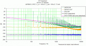
The amount of ripple is read from the height of the 120Hz peak on the plot. Going into the regulator it is -16dB, on the output it is reduced to -72dB. The ripple rejection of the regulator is about 56 dB.
The green line shows the unregulated voltage. The measurement limit for this trace is 120dB, so the noise baseline above 1.3kHz is obscurred.
The orange trace shows the regulated voltage. Taken at a higher gain, the measurement limit is about 140 dB (plus some broad spikes at visible at 80Hz and 210Hz for example), so the drop in the noise floor at 1.3Khz is real - though some of the peaks visible are not.
The blue line is the output noise from the OP27, referred to the input to make it comparable with the datasheet noise figures, shown as the straight black line. The output noise is equal to the op-amp noise, except for some ripple... seen as the small peaks at 120hz and multiples of.
The pink trace is the datasheet PSRR projected over the opamps input noise. Above this line, power line noise will detected in the output, below it, not.
So you can see that while an unregulated supply would not be a good idea, the LM78M12 would be acceptible here if a little more filtering as made available to reduce the ripple before the regulator. The noise floor of the regulator is well below the limit of the PSRR at all frequencies up to 10kHz.
I'm making no comments at all about sound quality. This is just a measurement of the noise. Above 10khz, too, the situation is unclear.
/Richard
PS. measurement system: National Instruments PCI6229 multifunction DAQ. 16bit sampling, +-0.2V input limit (1V limit for the Vin trace) 250kHz sampling rate.
Attachments
For the sake of completeness, I should add that the negative rail of the OP27 is powered by a JRC 7912A and 100uF caps on the input and output. The harmonics on both the positive and negative rails potentially contribute to those seen on the blue trace of the OP27 noise.
The plot is intended only as a qualitative demonstration of how much noise exists on the power supply rails before and after 78xx regulation, how much of this noise is attenuated by the opamps PSRR, and how this compares to the intrinsic noise of the opamp itself.
/R
The plot is intended only as a qualitative demonstration of how much noise exists on the power supply rails before and after 78xx regulation, how much of this noise is attenuated by the opamps PSRR, and how this compares to the intrinsic noise of the opamp itself.
/R
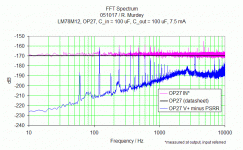
All the noise from the LM7812 output is technically present on the output of the OP27, but only the highest level peaks are stronger than the voltage output noise of the the op-amp itself.
In the plot below, I've subtracted the PSRR from the measured noise of the LM7812 output to simulate what it would look like at the output of the OP27. You can see that most of it is buried at least 10 dB below thw OP27s intrisic noise floor, and invisible so far as the measured output noise is concerned. In general there are more harmonics visible on the measured output than are predicted from just looking at the regulator output - this isnt surprising, really - but the correlation is pretty close, nonetheless.
/R
Dont know what the peak is at 4.7khz, or if its anything at all.
Attachments
thanks, this is interesting!
Some time ago, I compared some regulators, but just by listening to their noise via headphones and was surprised that onsemi's 7812s were quite a bit less noisy than Fairchild's, but the datasheets reveal the same. Try onsemi if you can get some!
Cheers,
Dominique
Some time ago, I compared some regulators, but just by listening to their noise via headphones and was surprised that onsemi's 7812s were quite a bit less noisy than Fairchild's, but the datasheets reveal the same. Try onsemi if you can get some!
Cheers,
Dominique
At some point I will get around to doing some more rigorous experiments. For the meantime, here is some real world data.
Basically, a Hitachi-branded LM78M12 clone drives the positive power pin of a Burr Brown OP27. The regulator has 100uF on the input and output terminals and the current draw is 7.5mA. The power supply is unregulated.
The amount of ripple is read from the height of the 120Hz peak on the plot. Going into the regulator it is -16dB, on the output it is reduced to -72dB. The ripple rejection of the regulator is about 56 dB.
The green line shows the unregulated voltage. The measurement limit for this trace is 120dB, so the noise baseline above 1.3kHz is obscurred.
The orange trace shows the regulated voltage. Taken at a higher gain, the measurement limit is about 140 dB (plus some broad spikes at visible at 80Hz and 210Hz for example), so the drop in the noise floor at 1.3Khz is real - though some of the peaks visible are not.
The blue line is the output noise from the OP27, referred to the input to make it comparable with the datasheet noise figures, shown as the straight black line. The output noise is equal to the op-amp noise, except for some ripple... seen as the small peaks at 120hz and multiples of.
The pink trace is the datasheet PSRR projected over the opamps input noise. Above this line, power line noise will detected in the output, below it, not.
So you can see that while an unregulated supply would not be a good idea, the LM78M12 would be acceptible here if a little more filtering as made available to reduce the ripple before the regulator. The noise floor of the regulator is well below the limit of the PSRR at all frequencies up to 10kHz.
I'm making no comments at all about sound quality. This is just a measurement of the noise. Above 10khz, too, the situation is unclear.
/Richard
PS. measurement system: National Instruments PCI6229 multifunction DAQ. 16bit sampling, +-0.2V input limit (1V limit for the Vin trace) 250kHz sampling rate.
very interesting behavior of this 12V tripod. The mentioned value of the used input and output caps are 100uF.
What kind of influence would have different quality standarts by this i00 uF caps so as an additional bypass cap?
Independend of this - many developers substitute the normal voltage regulators against a classic gyrator (e. g. 2N4401 small signal device, a 5K resistor from C to E and a capacitor from the base leg to GND)
Also a good solution is the use of a constant current source and two zeners in serial (junction of the zeners = GND). Now I have the great advantage to connect capacitors even with very large values in parallel zu each zener. The result is a accu-like voltage supply. The RIAA phono head amp NAD "PP-2" uses this voltage regulation topology (see attachement).
Attachments
Also a good solution is the use of a constant current source and two zeners in serial (junction of the zeners = GND). ... The RIAA phono head amp NAD "PP-2" uses this voltage regulation topology (see attachement).
That NAD circuit is mainly concerned with converting a 24 VDC floating input and converting it into a split 9 V supply for the NE5532 op-amp.
As a solution to that particular problem its elegant enough, but for DIY where a few extra dollars is not an issue it would be better to start with a split supply (dual output windings) and keep the positive and negative rails symmetrical.
Why do you think, split power supply (that means complete independend power supplies/voltage regulators for the positive rail and the negative rail, refer to GND) is a better solution than that with one floating assymmetrical floating voltage input ?? I cannot discover there clearly advantages
Last edited:
- Status
- This old topic is closed. If you want to reopen this topic, contact a moderator using the "Report Post" button.
- Home
- Amplifiers
- Power Supplies
- FFT Noise Spectrum of the LM7812 three terminal fixed voltage regulator

