I am wondering what the difference is between a center tapped transformer, and a transformer with dual secondaries?
I am looking to build a gc amp with two seperate rectifier bridges (as that is what comes in the kit), and I have read somewhere that in order to do this, one must have either 2 transformers, or 1 with dual secondaries. Will a single, center tapped transformer work? Ie, is it possible to connect the center tap wire to both bridges?
In scenario b, say I were to use only one rectifier bridge, and I wanted an ac input (before rectification) of 22V. Would I want a 11-0-11 transformer or a 22-0-22? Would either work depending on how I wired it?
Thanks to anyone who can sort out my confusion.
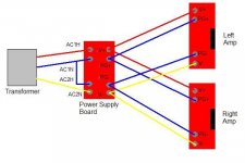
I have built a few power supplies with 2 bridges using CT transformers. It does seem to matter how you use the CT though. It would seem that (using the Brian GT boards nomenclature) you would wire one AC line to AC1H and the other to AC2H and then use the CT for AC1N and AC2N. When I tried that I blew fuses.
What I found that has worked for me is this-
AC1 from the transformer to AC1H on the board
CT from the transformer to AC1N on the board
CT from the transformer to AC2H on the board
AC2 from the transformer to AC2N on the board
Here is a diagram:
What I found that has worked for me is this-
AC1 from the transformer to AC1H on the board
CT from the transformer to AC1N on the board
CT from the transformer to AC2H on the board
AC2 from the transformer to AC2N on the board
Here is a diagram:
Attachments
Technically best one is parallel wound dual secondary, because two windings are exactly the same. Most of the center tapped transformer has one winding layered inside and the other one outside and that can create a different characteristic however I don't belive that will make practical differences.
To use dual secondary, when you have Va, 0a, Vb,0b, combine 0a and Vb which will works as center tab and goes to the ground level. Va goes to one AC in of bridge rectifier and 0b goes to the other AC in.
The rectifiers + and - out goes to the filter caps and to feed the amp.
To use dual secondary, when you have Va, 0a, Vb,0b, combine 0a and Vb which will works as center tab and goes to the ground level. Va goes to one AC in of bridge rectifier and 0b goes to the other AC in.
The rectifiers + and - out goes to the filter caps and to feed the amp.

StalfoS said:My BrianGT kit came with two rectifier boards.. This made sense to me until i realized that each board had two bridges on it. What is the purpose of having 4 rectifier bridges?? Can someone explain? Circuit diagrams would be super helpful.
Cheers.
One board is "extra" if you are building a stereo (if you put both amp boards into a single case with a single power supply).
You use it if you build monoblocks (i.e. if you put each amp board in its own case with its own power supply).
Actually you could also put both amps in one case and still give each its own PS but I think that is overkill.
Same problem here: I could use an existing center-Tapped transformer instead of buying two secondaries.
Using it with a dual power supply that uses two rectification circuits means:
The center tap will NOT be connected to ground. It is the wire both windings share.
AC H /N have to be identified for correct connections.
But how do I identify H/N using two bridge rectifiers and
how do I identify H/N using single diodes?
If I understand you correctly you are using a CT secondary to feed a PSU board which has two bridges, one per polarity, intended for use with two separate secondaries. As you found, if you wire it wrongly you can blow fuses. If you wire it correctly then it will work (sort of) but you will only get half-wave rectification so extra ripple and a hotter transformer. Not a good idea, unless you really need to avoid buying the right transformer and/or the right PSU PCB.Sherman said:I have built a few power supplies with 2 bridges using CT transformers. It does seem to matter how you use the CT though. It would seem that (using the Brian GT boards nomenclature) you would wire one AC line to AC1H and the other to AC2H and then use the CT for AC1N and AC2N. When I tried that I blew fuses.
What I found that has worked for me is this-
AC1 from the transformer to AC1H on the board
CT from the transformer to AC1N on the board
CT from the transformer to AC2H on the board
AC2 from the transformer to AC2N on the board
Primarily, this is the same. With two secondaries you'd connect them at one end and have the same result. Same transformer or separates even.I could use an existing center-Tapped transformer instead of buying two secondaries.
The secondaries are better when matched, as mentioned earlier, but don't confuse DC balance with AC balance.
Can you explain this please?Using it with a dual power supply that uses two rectification circuits means:
The center tap will NOT be connected to ground. It is the wire both windings share.
If the transformer have dual secondaries you may use it at least 3 different ways
1- put them in parallel, you will have the nominal voltage but will be able to feed twice the current.
2- put them in series, you will double the voltage but will be able to feed only nominal the current.
in both case you have to care about phasing.
3- use them in 2 different circuit '' floating '' from each other.... this is what you need to do for a '' dual bridge '' power supply. And this configuration cannot be done with a center tapped tranformer.
There are several reasons why dual bridge is better, and some was mentioned earlier. One more reason - we can use low (or lower) Vf Shotky diodes and get a little higher output voltage with colder diodes (higher efficiency).
And one more strong reason - it can give potential ability to do (to make?) path of caps charging curents fully isolated from load currents. It means less 100/120 Hz hum. Sometimes it makes magic.
So when I have a choice - I prefer separate secondary windings - it gives "posibilities".
And one more strong reason - it can give potential ability to do (to make?) path of caps charging curents fully isolated from load currents. It means less 100/120 Hz hum. Sometimes it makes magic.
So when I have a choice - I prefer separate secondary windings - it gives "posibilities".
Last edited:
- Status
- This old topic is closed. If you want to reopen this topic, contact a moderator using the "Report Post" button.
- Home
- Amplifiers
- Power Supplies
- Center Tap vs Dual Secondaries