Flyback -v- Input Rectifiers
The Input Rectifiers are ultrafast types, because of the hi-frequency pulses being drawn through them. Let me clarify this- the diodes are conducting high-frequency pulses, modulated at 120Hz (the rectified haversive frequency here in the States, 100Hz overseas).
The flyback diode need not be an ultrafast type, but I chose the flyback to be ultrafast because the input units already were. Perhaps I will change this in the future
Steve: I do not doubt that flyback diode switches at PFC frequency ")
I just wanted to point at diode current waveforms for different operation mode of PFC.
In fixed-frequency PFC like my favorite L4981A this diode conducts current more similar to square form with triangle superimposed; that is at turn-off moment it has to cut quite significant current very quickly (because at this moment FET switch is beginning to conduct, passing the baton of inductor current, so diode must not short it to outpur capacitor!)
On the contrary, critical-conduction PFC draws pure triangle current waveform thru inductor, that is requirement to diode off-state recovery time is not that strict.
You can see different diode production types, called like "fast", "ultrafast", "hyperfast" etc. on IR, OnSemi and the like manufacturers' websites.
So I just meant that MC34262-based circuit can be satisfied with mere "fast" diode (200-250ns recovery) but for example L4981A-based one definitely needs "ultrafast" (35-50ns recovery).
So what do you supply with your PFC?
Alme said:So what do you supply with your PFC?
I'm not sure I understand this question, but here goes:
If you're asking what kind of power do I supply it with, here in the 'States, most American (and Canadian) are wired for 120/240V, 60Hz. We have 240 by virtueof center-tap gorunding, giving two out-of-phase 120V legs. I do have the opportunity to explore inputs at 240V, though I haven't done this, yet.
If you're asking how I am running the control, it's definitely critical conduction mode. I realize that this is NOT fixed-frequency, ans I would like to explore a fixed-frequency type of PFC, as this would greatly facilitate synchronizing the PFC to the PWM, eliminating beat frequencies between the two converter stages.
If I haven't answered your question, please clarify it. Thanks Alme.
Steve
Well, Steve, my question was about the purpose of your PFC
I suppose it wasn't created just for itself, or did you just try it to learn?
By the way, synchronizing modules is a really great thing. Yesterday during test of my current switching amlifier, I synch'd secondary oscillator (LM393-based) with primary converter SG3525 and immediately got residual noise improvement by 12dB! This is pretty easy done with 20-cent optocoupler.
PCF Purpose
Alme,
OK, I've got it now. The purpose of this PFC was to pass my senior project class for my undergraduate degree, now, going on more than a few years ago!
I had hoped to power a DC-DC PWM Section, either MC33025 or SG3525-based, but with the fuse blowing right away, I decided againse it for now. BTW, how big a fuse is recommended for the input? This is PFC rated for 180W. (The boost coil is made by Coilcraft specifically for operation with the '33262.) I believe I was running with a 4-5 A Slow-blow, and it still blew. Until I get a decent-sized isolation transformer for safety reasons, I am holding off any further high-voltage or AC Mains-powered ckts.
That's pretty sweet on the synchronizing thing! 12dB drop in noise, it's a beautiful thing!
Steve
Alme,
OK, I've got it now. The purpose of this PFC was to pass my senior project class for my undergraduate degree, now, going on more than a few years ago!
I had hoped to power a DC-DC PWM Section, either MC33025 or SG3525-based, but with the fuse blowing right away, I decided againse it for now. BTW, how big a fuse is recommended for the input? This is PFC rated for 180W. (The boost coil is made by Coilcraft specifically for operation with the '33262.) I believe I was running with a 4-5 A Slow-blow, and it still blew.
Until I get a decent-sized isolation transformer for safety reasons, I am holding off any further high-voltage or AC Mains-powered ckts. That's pretty sweet on the synchronizing thing! 12dB drop in noise, it's a beautiful thing!
Steve
PFC preconverter
Hi N-channel
Attached is the schematic of the PFC preconverter I use in my PowerDAC2 digital amp since 2003. It's rated at 760W from universal input mains and is really nothing novel i.t.o. PFC technology. The control chip used is the L4981 chip from ST which really is a fine device - it's basic, but robust and does exactly what it says on the tin, so I've not been motivated to move to the newer chips that promote slightly more efficient switching at the expense of higher component count.
The L4981 is able to vary the PFC frequency within a small range in order to 'spread' spectral peaks that could otherwise violate EMC norms. Switching frequency varies downwards from 145kHz to (I seem to remember) about 115kHz. Note that the fs is always below 150kHz so that the fundamental is excluded from EMC measurements, yet is high enough to allow a Magnetics Mollypermalloy toroid core to be used for the boost inductor, which also helps keep emissions down. I can post details of this if there's interest.
It might be noticed that at 500uF the design is a liitle 'thin' on storage cap value; I was able to get away with this because the PFC feeds a 385:72V dc:dc block of 2 series'd 2nd generation Vicor converter 'bricks' that operate down to below 300V. (I had these available and didn't have to sell my car and house to buy them) The predecessor of this PFC had more storage capacitance and was used to feed a 750W ZVS full bridge converter.
The 12V supervisory supply was obtained from a separate 5W universal input switchmode supply that was used to power standby circuitry.
Finally, I feel obliged to say this - many of us know this, but not all do:
WARNING: The circuit attached is not isolated from the mains and should not be built or tested without a suitable isolation transformer, or used to power any other circuitry or device that does not provide isolation. The circuit should not be built by persons not familiar with CE or UL safety regs.
Hope this is of interest.
Cheers
John
Attachments
John Hope, thanks for sharing experience! It is of much interest to me; I have tried only fixed frequency type of L4981 (A index) before. For higher power application (about over 500W) they suggest to include small inductor (4-8uH) and snubber/clamper in series with FET drain, for any conduction mode PFC, but recently I couldn't find that application note on ST website.
Can you please recall or estimate power loss/efficiency of your PFC? What is the component with highest losses there - FET, or diode, or maybe inductor? What you think is better to use as main switch at such power level, MOSFET or IGBT? My calculation shows that IGBT is going to have lower static (on-state) losses, but I'm not sure about switching losses at such frequency. Supposing if to use the fastest IGBT type currently available
Can you please recall or estimate power loss/efficiency of your PFC? What is the component with highest losses there - FET, or diode, or maybe inductor? What you think is better to use as main switch at such power level, MOSFET or IGBT? My calculation shows that IGBT is going to have lower static (on-state) losses, but I'm not sure about switching losses at such frequency. Supposing if to use the fastest IGBT type currently available
Hard switching at such high frequencies ~150Khz causes most of the losses to concentrate on the switch. In these circumstances MOSFETs are preferable
I'm using IGBTs but my operation philosophy is different since my circuit uses soft switching at 45Khz with controlled dI/dt. This forces to use a bigger inductor but allows for smaller heatsinks, power devices and EMI filter
I'm using IGBTs but my operation philosophy is different since my circuit uses soft switching at 45Khz with controlled dI/dt. This forces to use a bigger inductor but allows for smaller heatsinks, power devices and EMI filter
PFC Schemo
John,
Wow! That's quite a write-up and a good schematic! I, too, am interested in the power losses at the 115-145kHz region, and would include in the power loss question the sensing resistor. What is its value and power loss? I'm glad you followed up with the external EMI filter comment, because that was to be my first question. Also, what is the lowest input AC voltage you have tested it to? 85VAC? What was the highest? 264VAC? This would really be a robust design, if it could maintain max outout power at lowest line (85VAC) with only moderate losses. What is the value of the coil? The part number on it is kinda confusing.
I am a little confused, though- your schematic has the L4981 run variable-frequency, yet Alme uses it in a fixed-frequency mode. Is this possible with the same chip, or did I miss something in the L4981's application notes?
Great work!
Steve
http://www.diyaudio.com/forums/attachment.php?s=&postid=629868&stamp=1114677004
I notice you are using mini melf for R48/50......am I right these are rated for 50mW ?
I'm currently up dating my 800W schematic.......more later.
There is very little EMC combat on both in/out. Note to get through compliance I had to resort to biscuit tin / RF techniques/ with ceramic feedthroughs.
richj
Attachments
N-channel :
There are two versions of the L4981 :
- The L4981A features fixed frequency and an additional input to the multiplier for load feed forward [LFF] purposes, allowing the input current amplitude to track the load current waveform for better transient response
- The L4981B features variable frequency but lacks the LFF function because that pin of the IC is used as a frequency modulation input
The B version seems to me quite hard to find
Thanks for explanation Eva
I think what you call controlled dI/dt switching process (I saw your schematic idea) is alike that simple solution from STM to include small series inductor plus D-R-C into FET drain. I'm not sure if it's clear from verbal description so include its picture.
I think what you call controlled dI/dt switching process (I saw your schematic idea) is alike that simple solution from STM to include small series inductor plus D-R-C into FET drain. I'm not sure if it's clear from verbal description so include its picture.
Attachments
Eva said:N-channel :
The B version seems to me quite hard to find
Hi there.........try Farnell part number 323-6092
richj
PowerDAC PFC questions
Here are some answers to questions asked:
1. The inductor is called 235U14A55439. This is my own part number for a 235uH 14A max inductor on a Magnetics 55439 MPP toroid.
2. The MELF resistors are BC Components MMA0204 professional series available from Farnell. They're rated at 0.25W, have 28W pulse load capacity, 200V max voltage and best of all, fit on a 1206 footprint. I use these for all R which are subject to HV (as in this PFC) and those subject to pulse loading. (eg carrying hf charging pulses to a big electroilytic cap in a PFC bootstrap supervisory supply). I've had ordinary resistors fail in these pulse applications.
3. The current sense resistor is 0.033 ohms 4W. Assuming 95% efficiency, it has to handle 2.92W when the PFC is delivering 760W from 85V rms mains. Yes, this is wasted power, but the alternatives didn'rt appeal to me at the time on the grounds of component count or complexity.
4. In the course of hobby and work I've built PFCs from 300 to 1000W, some of which have been EMC qualified and are produced in volumes of 2000 per year. What I found i.t.o. EMC is that the boost inductor is a Major Felon when it comes to generating EMI and anything other than a toroid wound with a single layer is going to make your life difficult, as you want to minimise the distributed capacitance between windings. There's a good ST app note on this. It's this capacitance which lets RF currents from the switch sail back towards the mains.
It was the requirement for a single layer toroid that drove my design to use the 120-145kHz switching frequency, which would otherwise be considered too high for a hard switcher.
5. Note the snubber on the gate drive. This was because I'd found on other PFCs that there's a tendency for very small amplitude ringing of about 200-250MHz on the gate drive signal at precisely the switching point; this translates to ringing on the FET drain voltage and generates conducted RFI.
Even if you're a DIYer, you should care about EMC to the extent that you don't willfully employ design practices known to be EMC unfriendly. It's like making things you know are unsafe.
6. The PFC efficiency of this hard switcher was assumed to be 95% for design - you have to assume something during the design otherwise you can't work stuff out - and in practice it measured about 92-93% at 240V mains.
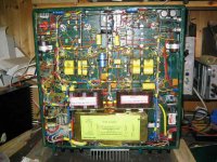
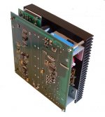
I can't answer the other questions until I dig out my design calcs, which I will do on thwe weekend. I've attached a pic of the PSU module, which includes PFC, isolated dc:dc bricks for 72V 700W, as well as supervisory regulators for 5V 4A, 3.3V 1A, +12V 1A and -12V 0.5A
One aspect where I slipped up on this PSU was on the heatsink. Because it formed a convenient mounting base for the dc:dc bricks, I ended up with a horizontal heatsink, ie with the channels between the fins horizontal. In this orientation, removal of heat through convection is very poor, and at full load the PSU heatsink equilibium temp measured 85C, whereas it's less than 45C when mounted vertically. I ended up making a brace of four 40mm lo-noise fans (5mm high) and fitting these atop the heatsink with an acoustic insulator. The fans spool at the laziest rpm they can without stopping, but they provide sufficient airflow to replace 'proper' convection and the heatsink temp is below 40C always.
Regards
John
Here are some answers to questions asked:
1. The inductor is called 235U14A55439. This is my own part number for a 235uH 14A max inductor on a Magnetics 55439 MPP toroid.
2. The MELF resistors are BC Components MMA0204 professional series available from Farnell. They're rated at 0.25W, have 28W pulse load capacity, 200V max voltage and best of all, fit on a 1206 footprint. I use these for all R which are subject to HV (as in this PFC) and those subject to pulse loading. (eg carrying hf charging pulses to a big electroilytic cap in a PFC bootstrap supervisory supply). I've had ordinary resistors fail in these pulse applications.
3. The current sense resistor is 0.033 ohms 4W. Assuming 95% efficiency, it has to handle 2.92W when the PFC is delivering 760W from 85V rms mains. Yes, this is wasted power, but the alternatives didn'rt appeal to me at the time on the grounds of component count or complexity.
4. In the course of hobby and work I've built PFCs from 300 to 1000W, some of which have been EMC qualified and are produced in volumes of 2000 per year. What I found i.t.o. EMC is that the boost inductor is a Major Felon when it comes to generating EMI and anything other than a toroid wound with a single layer is going to make your life difficult, as you want to minimise the distributed capacitance between windings. There's a good ST app note on this. It's this capacitance which lets RF currents from the switch sail back towards the mains.
It was the requirement for a single layer toroid that drove my design to use the 120-145kHz switching frequency, which would otherwise be considered too high for a hard switcher.
5. Note the snubber on the gate drive. This was because I'd found on other PFCs that there's a tendency for very small amplitude ringing of about 200-250MHz on the gate drive signal at precisely the switching point; this translates to ringing on the FET drain voltage and generates conducted RFI.
Even if you're a DIYer, you should care about EMC to the extent that you don't willfully employ design practices known to be EMC unfriendly. It's like making things you know are unsafe.
6. The PFC efficiency of this hard switcher was assumed to be 95% for design - you have to assume something during the design otherwise you can't work stuff out - and in practice it measured about 92-93% at 240V mains.
I can't answer the other questions until I dig out my design calcs, which I will do on thwe weekend. I've attached a pic of the PSU module, which includes PFC, isolated dc:dc bricks for 72V 700W, as well as supervisory regulators for 5V 4A, 3.3V 1A, +12V 1A and -12V 0.5A
One aspect where I slipped up on this PSU was on the heatsink. Because it formed a convenient mounting base for the dc:dc bricks, I ended up with a horizontal heatsink, ie with the channels between the fins horizontal. In this orientation, removal of heat through convection is very poor, and at full load the PSU heatsink equilibium temp measured 85C, whereas it's less than 45C when mounted vertically. I ended up making a brace of four 40mm lo-noise fans (5mm high) and fitting these atop the heatsink with an acoustic insulator. The fans spool at the laziest rpm they can without stopping, but they provide sufficient airflow to replace 'proper' convection and the heatsink temp is below 40C always.
Regards
John
Attachments
What's that?
PS: The big heatsink-mounted resistors you can just see under the PCB are voltage dependent load dumpers on the +72V rail. In a digital amp where PSU voltage is used to control volume, if the volume is reduced by reducing the voltage of the sync reg, current flows backwards through the sync reg to the +72V raw supply and builds up voltage on caps on the 72V bus. To keep this buildup to reasonable limits one has to fit clamps or a switchable load on the +72V raw supply. In my first PowerDAC I used a series string of 3 x 5kW TransZorbs as a clamp; in this design I switch in a phat load.
Cheers
John
Alme :
This circuit dissipates in a resistor all the energy stored on the inductor on each pulse
With 5uH at 45Khz and 25A peak [2KW at 160Vrms including diode reverse current] the dissipation on the resistor would be 70W so it's not practical
However, my circuit uses a coupled inductor to transfer that energy to the output capacitor so it's almost lossless
To Eva: I'm not sure about that stuff, how to define power loss in such snubber, but I've seen 0,5W resistor is used there in some professional design and I also used such resistor without a problem (PFC output power 300-400W, switching freq. 100kHz, input voltage 180-240VAC)
- Status
- This old topic is closed. If you want to reopen this topic, contact a moderator using the "Report Post" button.
- Home
- Amplifiers
- Power Supplies
- PFC Switched-Mode Power Supply