Hello Everyone,
I have just built a soft start circuit based on Rod Elliott's (Soft-Start Circuits).
The circuit is based on Figure 5, Auxiliary Transformer Control Circuit.
All components are the same with exception of R1, which I am using 68kR.
The resistor bank comprises 3 x 180R 5W which would limit inrush to 4A.
The question is the relay click almost instantaneously when I turn on the power, and there is no delay at all. While I do not have a proper measuring instrument to measure the time delay but I know I can tell if it is 100ms, but it is not.........
Rod Elliott's article suggest that there is a co-relation between the value of R1 and the gate threshold voltage of Q2 (2N7000). For my case the gate threshold voltage is 2.3V (measured with DCA55).
Can someone advise if the value of R1 should be increased or decreased based on my current situation?
Many thanks.
Yes, some parts of the text can be a bit confusing. The schematic shows 56kR but some text mentioned 27kR.
My understand after reading through multiple times is that R1 should generally be between 27kR~68kR. When Q1’s gate threshold voltage is exceptionally low then R1 may need to go beyond 68kR. Example given is that what gate threshold voltage is low at only 0.8V, R1 needs to be 82kR.
I hope I’m readying this correctly…………
Maybe this passage from a different soft-start PCB design thread, might provide a little food for thought:
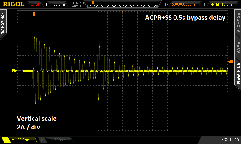
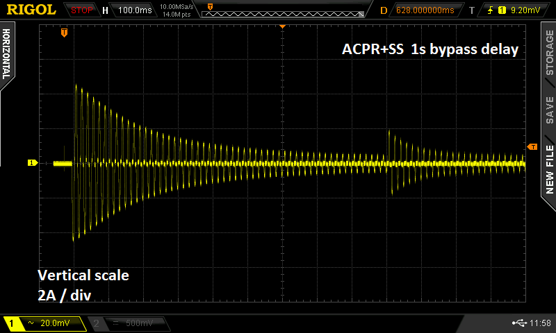
When should the inrush limiting cease? When should the bypass turn on? Opinions vary. Texas Instruments bypasses the ICL when the amplifier's DC power rails have ramped up to approx. 60% of their final voltage (Fig.5 on p.7). Douglas Self's textbook suggests bypassing 1 second after power-on (p. 632). Rod Elliott's inrush current limiter for power amps, Project 39, enables the bypass after 0.1 seconds. A brief and incomplete survey of diyAudio discussion threads, turns up recommendations varying between 10 full cycles of the AC mains (0.2 sec) and 100 cycles of the mains (2.0 sec). All of this suggests to me that there are probably more than one right answer, and maybe the shrewd decision is to provide a few user-selectable options. As has previously been done in the Soft As A Feather Pillow soft start design by diyAudio members jhofland and xrk971, I chose the convenient 2X-per-step settings 0.5 sec, 1.0 sec, 2.0 sec. Thus bypass happens either 0.5, 1.0, or 2.0 seconds after power on, selected by a jumper on the PCB.
The question is the relay click almost instantaneously
The article specifies 150mS delay. For us humans that qualifies as 'almost instantaneously', so there is probably nothing wrong.
Jan
...advise if the value of R1 should be increased or decreased based on my current situation?....
A bigger resistor takes longer to fill the capacitor.
A bigger capacitor takes longer to fill with the same resistor.
The MOSFET gate is a very high impedance. This suggests a very high resistance. I would try a 1Meg there. But this requires a low-leakage capacitor. It may be better to try 1uFd film capacitor and 10Meg resistor.
Another possibility is that the first time Q1 charged C2 with "infinite" current, Q1 blew short. IMHO, a design oversight. Now it WILL start "instantly".
It will work, not as well, with Q1 removed. If that makes it "delay" instead of "instant", Q1 may be blown.
My version of that circuit sounded instantaneous to me too so I measured the current across the current limiting resistor with my oscilloscope on single shot mode.
Took a bit of fiddling to get it to trigger right but it turned out that what I thought was instantaneous was in fact the 150ms I had calculated.")
Took a bit of fiddling to get it to trigger right but it turned out that what I thought was instantaneous was in fact the 150ms I had calculated.
I know this may sound a bit silly, but as I don’t have a proper measuring equipment (and don’t know what to use and may not know how to use one), I have one hand rested on the relay, and the other on the switch, and when I turn on the switch the relay just click at the same time. If I use a digital stop watch and do a super fast start stop, the fastest I achieved was 0.12ms and the motion of start stop is definitely much slower (relatively) than the activation of the relay in my current setup. My wife gave me that strange glare…………
This in the end is a learning for me, and I wanted to find out if it is worth experimenting with different values of R1. Finding electronic parts here is just so inconvenient so I need to limit the variation and number of parts I need to play around with.
If I could adjusting the timing with just different values of R1, I may just get a trimmer pot to try.
Last edited:
Can we just add a word of caution here as connecting a scope across the limiting resistor was mentioned.
That is highly dangerous and at face value would go BANG as the switched side is live and the scope should (any mains powered scope) be grounded. Do not even think of doing that.
One trick you might try is to increase R1 to 560k and see if you get a second or more delay.
As drawn the circuit will work as advertised and the delay will be correct. You only need a very short delay for the transformer to build up enough flux to limit the inrush current, any longer might 'feel' and sound good but serves no purpose beyond stressing the resistor bank.
If I use a digital stop watch and do a super fast start stop, the fastest I achieved was 0.12ms .
Or 0.12sec? 120us seems awfully fast for a moving finger.
Jan
Or 0.12sec? 120us seems awfully fast for a moving finger.
Jan
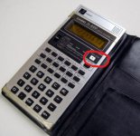
Jan, I have a Casio FX8000 calculator from college days that has a timer and stopwatch on it and we used to amuse ourselves seeing how quickly we could press start and stop.
80ms was the target to beat as I recall, in fact I still have it and it still works... yep about 80ms. 100 to 150 was more typical if you genuinely did two presses and did not 'bounce' the contacts.
Attachments
Oh, ok. Sorry, didn’t mean to give bad advice.................
Best to mention it
as someone somewhere might try it without realising the danger.Another way would be to connect the relay contact to the 12 volt rail rather than mains and then look on a scope at the supply vs delay rise times.
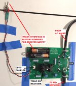
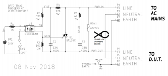
Attached below is a photo of the test rig I built, to observe mains inrush current limiters in action. It connects the mains to the Device Under Test, precisely at the zero-crossing of the mains voltage. This switching instant produces the worst case, maximum instantaneous peak value of inrush current. {remember "ELI the ICE man" from AC circuits 101? here he is again} Since I'm testing inrush current limiters, naturally I want to apply the worst case stress.
Being slightly paranoid about AC mains circuits, I included some safety features
This is the fixture I used to capture the traces shown in post #4, above.
_
Being slightly paranoid about AC mains circuits, I included some safety features
- Galvanically isolated, battery powered, human interface (test start switch)
- Galvanically isolated oscilloscope interface (non-contact current probe)
- Apparatus and I/O wires secured to insulated tabletop
This is the fixture I used to capture the traces shown in post #4, above.
_
Attachments
 and current clamps are great for things like that. The varistor looks very tiny.
Good eye! Yes I clicked on the wrong row of the parametric table and bought small diameter MOVs by mistake. Luckily (a) the PCB footprint accommodates several lead spacings; (b) the MOV doesn't really do much in this tester anyway. The RC snubbers deal with inductive flyback at switch-off , so the MOV is just a "belt and suspenders" safety net behind the main safety net. Protection against surges on the AC mains isn't much of a priority either, because the apparatus (inrush current measurement board) is only plugged into the mains for ~ 2 hours each year.
+1 for current probes/transformers. I built a current probe for measuring inrush current for about $10: The $10 Current Probe - How to Measure Current with an Oscilloscope – Neurochrome
As Mark pointed out earlier, the best way to set the inrush delay is to measure the current and tweak the delay such that the two inrush spikes (the initial and the one that happens when the inrush limiter is bypassed) are roughly equal. You will likely find that you can shorten the inrush delay considerably by using an NTC or inrush limiter rather than a power resistor in the soft start. If you do use power resistors, watch their peak power rating and make sure it's not exceeded. For more detail, have a look here: The Ultimate Guide to Soft Start Design – Neurochrome
Tom
Can we just add a word of caution here as connecting a scope across the limiting resistor was mentioned.
That is highly dangerous and at face value would go BANG as the switched side is live and the scope should (any mains powered scope) be grounded. Do not even think of doing that.
Yeah... Depending on how the BNC on the front panel of the scope is grounded that could be a fast way to ruin your scope as well.
Tom
- Home
- Amplifiers
- Power Supplies
- Soft Start Circuit - Too Fast Too Soon