I want to build the power supply with LR8N high voltage regulator assisted by IRF 830 as mosfet pass through.
The circuit is from wtfamp site.
l intended current is about 100 ma at 300 v.
What's the minimum input and output voltage differential?
What is the value of the zener BZX at mosfet?
Will the circuit work?
Thanks
The circuit is from wtfamp site.
l intended current is about 100 ma at 300 v.
What's the minimum input and output voltage differential?
What is the value of the zener BZX at mosfet?
Will the circuit work?
Thanks
Attachments
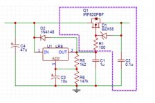
vout=(r2/r1)*1.2=150v approximately, not 300 - from LR8 datasheet
the zener is to protect the mosfet gate which cannot stand more than 20v between gate/drain, so 12v zener
LR8 requires min 12v across plus mosfet needs at least 4 to 5 v to conduct plus some drain/ source v
you also need some headroom in case input has ripple
e.g. if ripple is 10 v + 12v + 5v = 27v plus input v variation from mains ... so differential 35v or maybe more
will work under such conditions but 150 v out, not 300.
don't forget mosfet needs heat sink for dissipation W=(current * diff volt)
Last edited:
The Zener from gate to source of the MOSFET is merely an over-voltage protector to prevent gate-to-source insulation breakdown. 20Vdc or more across those two nodes will usually ruin the transistor. Since the MOSFET typically operates with about 3Vdc to 5Vdc G-S, a 6.8Vdc to 12Vdc rated Zener is fine. In normal operation of the circuit, the Zener does not conduct. The diode protects the MOSFET from transients that may occur at turn on & off of the unit it's in.
I have been a proponent of the LR8 in the past, but am now convinced that you are much better off with a Maida regulator, Tom's LT3080 based HV regulator or Jan's T-Reg.
The LR8 is best employed for SMPS startup circuitry -- see the application notes.
I want to point out an underappreciated issue in the circuit shown in post # 1.
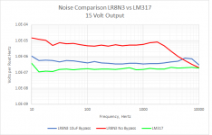
The ref voltage of the LR8 is very low, only 1.2V, and to get up to a high output voltage, the gain around it must be very high. In #1 it is 147k/1.2k which is 122.5 or almost 42dB. That means that all the nice specs in line and load regulation and noise given in the data sheet are more than 100 times worse in the #1 circuit.
In the #1 circuit the regulator output is buffered, so it may be acceptable.
The specific reason I developed the T-reg was to get rid of this disadvantage of 'conventional' high voltage regulators.
In the T-reg, there is no loop gain or performance penalty from the output voltage setting.
Jan
Last edited:
I want to point out an underappreciated issue in the circuit shown in post # 1.
The ref voltage of the LR8 is very low, only 1.2V, and to get up to a high output voltage, the gain around it must be very high. In #1 it is 147k/1.2k which is 122.5 or almost 42dB. That means that all the nice specs in line and load regulation and noise given in the data sheet are more than 100 times worse in the #1 circuit.
In the #1 circuit the regulator output is buffered, so it may be acceptable.
Doesn't the decoupling of the ADJ resistor solve that, except for deep subsonic frequencies? By the way, the LR8 has no noise specs, nice or otherwise.
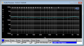
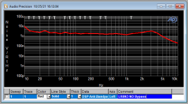
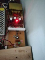
Testing the build
Testing the build on breadboard. Minimum hum and hiss on full volume. This maybe due to other components in the set up.
The heatsink for IRF 830 runs about 60 deg C at 315 input and 285 v output . Approximately 60 ma
Testing the build on breadboard. Minimum hum and hiss on full volume. This maybe due to other components in the set up.
The heatsink for IRF 830 runs about 60 deg C at 315 input and 285 v output . Approximately 60 ma
Attachments
- Home
- Amplifiers
- Power Supplies
- High Current high voltage for tube amplifier and preamp