I would need some documentation/formula regarding inductors on EI laminated iron core, where the "I" lamination is missing or removed.. These are sometime called "E-core open ended chokes".
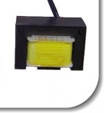
Many hi-current chokes, or inductors, in the market are built on EI lamination with gap to prevent saturation, some are built on just the I lamination (for speakers' crossover), and a few others (to which I'm interested) are built on E-core like this in the image, which is described as "open ended" thus approaching an air core choke performance, with flat inductance reponse.
In particular I would like to roughtly estimate how much factor the inductance will decrease moving from an EI-core inductance (usually with gap) to an E-core open ended inductance, once I have removed the "I" lamination
Attachments
Last edited:
Computing the decrease compared to a ~closed magnetic circuit would be difficult, but it is possible to compute the absolute inductance, based on first principles.
Inductance is the reciprocal of reluctance: R=l/(µ*A)
l is the length of the magnetic path, A is the effective magnetic area and µ is the µr*µo product, with everything in SI units.
Determining A is a no-brainer: it is the geometric area of the center-pillar, minus ~10% or so of stacking factor.
Because iron has a permeability so much larger than vacuum or air, the reluctance of iron can be neglected, leaving only the air-path. I guess you can approximate this path by drawing a half-circle between the centers of the center-pillar and one the outside legs.
This will give you the average length of the lines of the magnetic field, l.
Similarly, µr can be neglected, thus µ=µo.
You now have to scale the formula according to the number of turns.
The final result will thus be L=4*Pi*10E-7*A*N²/l
You need to know N, obviously. If you have no clue, you can change your inductor into a transformer by adding the missing "I" member, and compute the turns ratio by measuring the voltage from a 1 turn test winding with the inductor driven by a calibrated AC voltage.
As usual with magnetic calculations, the result will be approximative: iron does not have a zero reluctance, fringe fields have a heavy influence, and the winding has finite dimensions.
This will get you in the right ballpark though, and if you need to refine the inductance value you can always add or remove a few turns
Absolute measurement of incremental L with ac over a wide frequency range is also fairly easy with a soundcard setup for impedance measurement using software like REW.
A relatively simple test setup can measure absolute incremental L for a combination of ac and dc current levels (as per power supply choke performance) at 2x mains frequency.
You can then experimentally determine open and closed magnetic circuit conditions, and set up some known gap distance conditions to get a prediction plot of the gap needed for a desired inductance.
The coil fails, but mostly the contacts get pitted and useless.
Spare contact kits were available, now no longer.
So these get scrapped.
The coil is part of the armature, supply makes the contacts come towards the coil.
Supply off makes it go back with spring force.
So you remove the coil in its housing from the back of the unit, and there is your choke on an E lamination.
The I is inside, removing it takes work.
Or you could do it with the coil in place, and out.
I think the inductor testing that Naresh is suggesting is using a contractor to provide pulses through the open core inductor to find out.
I would also be wanting to know what is the flux leakage to the environment (ie if you're going to need to shield it or place it far away!).
I would also be wanting to know what is the flux leakage to the environment (ie if you're going to need to shield it or place it far away!).
Exactly, or not.
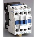
The contactor coil is the inductor, and comes with cores....
That is the item to be experimented with.
Without core, with E core, and with E-I cores.
He wants to see how the core affects inductance.
These are available almost free, to experiment with.
24 / 48 /110 /250 / 415 volts, some in DC are available.
Have fun.
Last edited:
I would need some documentation/formula regarding inductors on EI laminated iron core, where the "I" lamination is missing or removed.. These are sometime called "E-core open ended chokes".
Many hi-current chokes, or inductors, in the market are built on EI lamination with gap to prevent saturation, some are built on just the I lamination (for speakers' crossover), and a few others (to which I'm interested) are built on E-core like this in the image, which is described as "open ended" thus approaching an air core choke performance, with flat inductance response.
In particular I would like to roughly estimate how much factor the inductance will decrease moving from an EI-core inductance (usually with gap) to an E-core open ended inductance, once I have removed the "I" lamination
Not easy to answer and not that useful anyway because you have no clue on original gap and other EI inductors will be built different anyway.
So forget the original one, I´d rather design/measure/build a fresh one, which is the objective anyway.
Elvee goes straight to the E only problem solution and will give you a close estimate.
Trobbins suggests measuring the one you have, perfect.
Personally I would wind a bobbin with, say, 100 turns, slip the E core in, measure inductance, and then scale up/down as needed knowing inductance follows the square of the turns ratio.
IF curious, I would then add a stack of I´s to close the path and remeasure, slight problem is that rough stacking by hand is not very accurate, so E results will be trusty and repeatable; EI ones not so much.
You may slip different thickness paper/Mylar/kapton sheets for more predictable gap.
Naresh suggested experimenting on an EI inductor which apparently is easy to find around in India ... same here where stuff gets recycled or repurposed a lot ... not so sure it happens often where you live, where broken stuff goes straight to the junk bin
")
An extra problem is that discarded contactors are easy to find in heavily industrialized areas, with lots of Factories around within walking distance ... not that much in modern USA
Last edited:
The photo he posted was like the coil in a contactor.
I have saved some old contactors, because I am a pack rat...lots of tiny springs, long springs and so on.
Now it is cheaper to use SSR, and they are more reliable, so gradually their use is reduced, but in control circuits they are pretty common, as the different contacts are used in different parts of the circuit.
And motor starters too, those with thermal relays.
Even new, they are like $20 for a 4 amp control type, with 3 main and one auxiliary contact. just recently one was replaced on a KBA Rapida 104L offset printing press, new in 1998...Paid 3150 for 2 with extra contact blocks, as it needed 4 NO and 1 NC.
That is about 42 US Dollars.
Old ones or surplus ones will be silly money, and you get the laminated cores with bobbin included...
Last edited:
https://www.amazon.com/Packard-C230B-Pole-Contactor-Voltage/dp/B001KGSJ74/ref=sr_1_17?dchild=1&keywords=magnetic+contactor&qid=1635005015&qsid=141-1337924-5424137&sr=8-17&sres=B01KXVFJNI%2CB01KDPBU7I%2CB06X94QJK6%2CB01KXVR85A%2CB008XK54E6%2CB01LWXZXTH%2CB08T26LR6N%2CB00DEXSFIY%2CB01MSY6ZXW%2CB07QDM8XR1%2CB07J65Y55K%2CB07WHTX6P5%2CB001KGSJ74%2CB07YVMYBL8%2CB004ZRWGGA%2CB07H7TJ595
$11.11, and onwards... starting price is low.
Seems common in HVAC, so your HVAC repair shop may let you have them (old ones) for a small amount.
$11.11, and onwards... starting price is low.
Seems common in HVAC, so your HVAC repair shop may let you have them (old ones) for a small amount.
Last edited:
- Home
- Amplifiers
- Power Supplies
- EI Laminated Open Ended Inductors