Hi! I want to connect my microphone amplifier to a power supply. When I connect it to a 9 V battery I don't get any noise but when I instead connect it to a power bank which have 5V, there is a lot of noise.
Would it be possible to connect some sort of RC filter (low pass) after the power bank in order to filter out the high frequencies?
What cut off frequency will I use, or what values should I use for the resistor and capacitor?
Or is there a better fit for my purpose?
Thank you for your help!
Would it be possible to connect some sort of RC filter (low pass) after the power bank in order to filter out the high frequencies?
What cut off frequency will I use, or what values should I use for the resistor and capacitor?
Or is there a better fit for my purpose?
Thank you for your help!
9v and 5v. Does the amp work OK on 5v normally?
You can try adding an R/C filter or even two or more stages cascaded together. Much depends on the current draw of the amp as to values. Just experiment and choose R values that do not drop the supply voltage by much.
An L/C filter might be better at suppressing SMPS noise.
You also need to be sure that the noise isn't because of some ground loop when using the SMPS.
Tbh microphone amp and SMPS doesn't sound an ideal combination really.
To begin with, thanks for your answer, I really appreciate it!
On the amplifiers specification it says that it has a supply voltage from 3 - 12 VDC. Would it be a problem with 5 V then? Could that be a reason why it works better with a 9V battery?
Okay, I treid to add a simple first order RD filter, with a resistor of 47 ohm and a capacitor of 10 mF. That would give a cut-off frequency of 339 Hz, but it didn't help at all from what I could hear. I'm not sure what cut-off frequency to be around, but I was aiming at not lowering the output voltage to much. I guess I can try more options, and even a second order filter, maybe that would be better.
How can I check if the noise is because of ground loops?
And lastly, do you think it will be possible to solve this with the power bank that I already have, or would you recommend some other device for power supply? I'm not sure what would be best to have as little noise as possible from my diy microphone.
Thank you!
You're hearing the DC-DC converter in the power bank.
Since you said it works with a 9V, I would suggests using a 9V. Here's a link to some lithium rechargeables. https://www.amazon.ca/EBL-Lihtium-Batteries-Rechargeable-Lithium-ion/dp/B0756FVFH4
Since you said it works with a 9V, I would suggests using a 9V. Here's a link to some lithium rechargeables. https://www.amazon.ca/EBL-Lihtium-Batteries-Rechargeable-Lithium-ion/dp/B0756FVFH4
On the amplifiers specification it says that it has a supply voltage from 3 - 12 VDC. Would it be a problem with 5 V then? Could that be a reason why it works better with a 9V battery?
It depends on the amplifier and without knowing the circuit details we can't say for sure.
Normally a higher voltage means the ability to deliver a higher output voltage without running into clipping.
Okay, I treid to add a simple first order RD filter, with a resistor of 47 ohm and a capacitor of 10 mF. That would give a cut-off frequency of 339 Hz, but it didn't help at all from what I could hear. I'm not sure what cut-off frequency to be around, but I was aiming at not lowering the output voltage to much. I guess I can try more options, and even a second order filter, maybe that would be better.
10uF you mean
") If that made no difference then I don't think you are going to eliminate the noise going down this route. If it had made a significant change then worth pursuing, however...
If that made no difference then I don't think you are going to eliminate the noise going down this route. If it had made a significant change then worth pursuing, however...How can I check if the noise is because of ground loops?
That depends on the power supply and its connections and also the amp and its connections.
Have you tried running off battery and then:
1/ Just powering up the PSU and bringing it near the amp. Does it radiate interference?
2/ If the above was a clean noise free result then again power up by battery and this time connect just the negative of the running PSU to the battery negative. Does that now generate the noise?
If it does then the interference is probably entering via various 'leakage' routes but I suspect would be very hard to stop.
And lastly, do you think it will be possible to solve this with the power bank that I already have, or would you recommend some other device for power supply? I'm not sure what would be best to have as little noise as possible from my diy microphone.
Thank you!
A clean battery supply is always going to be the quietest for mic amp. If the current draw is low then a battery pack of some sort should be able to run it for many many hours.
If you want mains power then a traditional linear type supply would be best rather than a switching one.
Yes, I tried to connect it now with battery and connected from the power bank to ground. The noise is not there, so I guess it's not due ta any leakages from ground loops but because of voltage ripple?
Can you recommend anything to remove the ripple? Since a simple RC-filter did't work, I was thinking of either a linear regulator, a capacitor mulityplier or just using a battery. What would you recommend?
Thank you both for your answers!
Can you recommend anything to remove the ripple? Since a simple RC-filter did't work, I was thinking of either a linear regulator, a capacitor mulityplier or just using a battery. What would you recommend?
Thank you both for your answers!
Batteries have to be the cleanest. The problem with anything switching is that the noise/ripple has fast rise times and is very difficult to remove completely (at least easily).
The LC filter kodabmx and myself mentioned are the usual first line defence for reducing switching noise but whether it would be enough is difficult to say. You would have to experiment.
The LC filter kodabmx and myself mentioned are the usual first line defence for reducing switching noise but whether it would be enough is difficult to say. You would have to experiment.
I'm not good with scopes, so I can't tell what the frequency is. Once you know that, you can use an LC filter calculator to find the value.
Seriously though, rechargeable batteries are cheap and easy, and you know it will work already...
You could also try a car stereo filter, but I doubt you'll draw enough current for it to work. https://www.amazon.ca/Axxess-Line-N...49MWUMQ/ref=pd_lpo_1?pd_rd_i=B0049MWUMQ&psc=1
Seriously though, rechargeable batteries are cheap and easy, and you know it will work already...
You could also try a car stereo filter, but I doubt you'll draw enough current for it to work. https://www.amazon.ca/Axxess-Line-N...49MWUMQ/ref=pd_lpo_1?pd_rd_i=B0049MWUMQ&psc=1
The diyAudio Store sells a kit containing PCB + all parts, for cheap (USD 10). The kit is a filter which reduces SMPS high frequency noise. Read the enthusiastic reviews from members who bought and built and used the kit.
link to diyAudio Store sales page
If you follow the link on that page you can view the circuit's schematic diagram. It is an LCLC filter. Max allowed current is 3.0 amperes and max allowed voltage is 48 volts.
link to diyAudio Store sales page
If you follow the link on that page you can view the circuit's schematic diagram. It is an LCLC filter. Max allowed current is 3.0 amperes and max allowed voltage is 48 volts.
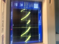
No mine haven't. but I could adjust the cursors so that it measured in x-led instead, see image.
Then it says that the frequency is around 4 Hz, but that tells me very little ...
Thank you for your reply, I will check out that circuit. Perhaps it can help me with what I'm aiming for. But like you said before, maybe I'll just go for batteries.
I haven't mensioned this before but fyi my amplifiers needs a supply voltage of 3-12 VDC and has a power consumption of 2.2 mA at 12 V.
Attachments
I was interested until 48V. 480V would be more appealing for me being a tube guy.
You have an SMPS wall wart that delivers 480V? Wow.
an inline DC filter for SMPS wall warts . Preamps, HPA, Korg NuTube, etc
Quite a few recent line-level projects here on diyAudio, are using Switch Mode Power Supply ("SMPS") wall warts to convert mains AC into the DC needed by audio circuitry. To name a few recent examples, the Starving Student II headphone amp, the First Watt H2 effects box, the B1 Korg NuTube preamp, and the Amp Camp Preamp+ (with headphone amp) are all powered by external SMPS warts. It's definitely a trend.
However, the 50-350 kilohertz switching circuitry inside SMPS modules, does make some members nervous. These folks are very concerned that high frequency noise on the DC supply, could compromise the sound quality of audio circuits. They desire a DC supply having very little high frequency noise, or, ideally, none.
Neither am I, hehe.
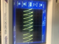
I'm not sure how to calculate cut off frequency from knowing the peak to peak voltage. And therefore it's hard for me to know what values to use.
Maybe @Mooly does?
I'm not even sure if to use a low-pass or high-pass LC filter anymore ....
Frequency is calculated by looking at the time period of one cycle. In other words look at any point on the waveform and move along until that same point occurs again. Then read the time off the bottom axis. Normally you would know how many milliseconds or microseconds the timebase is set for per division.
To calculate you find the reciprocal (divide the time per cycle into '1')
So taken at face value you have 250ms showing at the bottom.
Is that per division???
If it were then that would be 1/0.25 which is 4Hz and that kind of agrees with the other reading of <8Hz
So those kind of frequencies would not be related to a switching supply which would be more likely in the 40kHz to 150kHz range.
So a bit of a puzzle what you measuring there.
Attachments
No you are correct, I'm not sure what I measured.
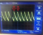
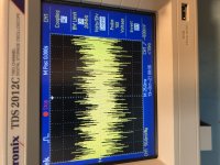
I did a new measurement which I've attached an image on. You can't say on the image but the scope showed around 2kHz when doing the measurements. Does that seem more accurate to what voltage ripple could be around?
So, I tried with new values for resistor and capacitance but I still got no improvement, only a more high frequency noise.
I'm going to try to create a LC filter instead. Hopefully that will work. Still confused though if I'm measuring the correct thing with my oscilloscope though.
Do you have any recommendations for the LC filter? For example which values of components, and so on
Thanks again!
Attachments
- Home
- Amplifiers
- Power Supplies
- Switch mode voltage from power bank, how to filter noise? Use for microphone with amp