Before going down the same road I already traveled, try a different power bank.
These things were made for charging phones, not powering sensitive audio equipment. They are not all the same and some can output nasty noise and glitches that filtering and even a second regulator stage will not remove.
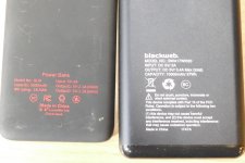
I got several power banks from the $1 and $5 bins at our local Walmart a few years ago. There were two kinds, the larger Blackweb brand (Walmart's house brand) and the smaller Think Geek brand with the Star Wars emblem on the front. I used them for charging camera batteries and all did good for that job, although none delivered anywhere near their marked capacity (common).
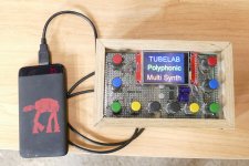
Last year I designed and built a small digital music synthesizer with an internal headphone amp which could be played with any MIDI keyboard and powered by a USB port. During the testing and development I wasted about 2 weeks trying to fix the random grumbling noise, buzzing, and random weird sounds that plagued the design. I even ripped out the original headphone amp and tried a different design. Both ran fine on a bench power supply, the USB port on two different laptops, or a 9 volt battery. They however were unusable on a power bank, or so I thought.
I had been using the larger Blackweb power banks so I wouldn't need to recharge often. One day both of the Blackweb's were drained, so I tried the small one. There was zero noise with three different power banks.
It seems that the power coming from the Blackweb banks is pretty dirty, and does have the low frequency sawtooth wave that you posted on it's output.
The frequency and amplitude of the "crud" changed with the load, and state of charge in the power bank, but did not go away until it was nearly drained. Attempts to clean this up with big caps and any size inductor that would fit in my small box were futile. I could only change the frequency.
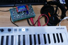
I have been using the little synth on the small power banks ever since. The synth and Keystep will run continuously for about an hour on one power bank. For longer playing time I power the synth and the Keystep from individual power banks.
These things were made for charging phones, not powering sensitive audio equipment. They are not all the same and some can output nasty noise and glitches that filtering and even a second regulator stage will not remove.
I got several power banks from the $1 and $5 bins at our local Walmart a few years ago. There were two kinds, the larger Blackweb brand (Walmart's house brand) and the smaller Think Geek brand with the Star Wars emblem on the front. I used them for charging camera batteries and all did good for that job, although none delivered anywhere near their marked capacity (common).
Last year I designed and built a small digital music synthesizer with an internal headphone amp which could be played with any MIDI keyboard and powered by a USB port. During the testing and development I wasted about 2 weeks trying to fix the random grumbling noise, buzzing, and random weird sounds that plagued the design. I even ripped out the original headphone amp and tried a different design. Both ran fine on a bench power supply, the USB port on two different laptops, or a 9 volt battery. They however were unusable on a power bank, or so I thought.
I had been using the larger Blackweb power banks so I wouldn't need to recharge often. One day both of the Blackweb's were drained, so I tried the small one. There was zero noise with three different power banks.
It seems that the power coming from the Blackweb banks is pretty dirty, and does have the low frequency sawtooth wave that you posted on it's output.
The frequency and amplitude of the "crud" changed with the load, and state of charge in the power bank, but did not go away until it was nearly drained. Attempts to clean this up with big caps and any size inductor that would fit in my small box were futile. I could only change the frequency.
I have been using the little synth on the small power banks ever since. The synth and Keystep will run continuously for about an hour on one power bank. For longer playing time I power the synth and the Keystep from individual power banks.
Attachments

I did a new measurement which I've attached an image on. You can't say on the image but the scope showed around 2kHz when doing the measurements. Does that seem more accurate to what voltage ripple could be around?
That looks more like broad spectrum noise. You could try something a 10uH and a 47uF or 100uF cap but I suspect the thing is just going to be to noisy to be partnered with a mic preamp.
I see. I'm going to try at least. I do not have any 47 uF or 100 uF, I only have 10 uF. Can I go with that and an inductor around 100 uH?
Do you think the broad spectrum noise is only due to a bad power bank? Or could it be something like bad soldering, to long wires etc?
Thanks!
Do you think the broad spectrum noise is only due to a bad power bank? Or could it be something like bad soldering, to long wires etc?
Thanks!
I tried .... with the settings that I wrote about in my previous post, and the result was interesting. From what I can hear, the noise got better but instead the amplification (at least I think?) got worse.
It sounds almost as I'm in a box when doing recordnings. Why is that? Is it because I lower the voltage too much when using a LC-filter with these values for components ( 10 uF and 100 uH)?
I'm a beginner as you can tell, so I'm just trying to learn and get as good result as possible without using a battery ....
I'm a beginner as you can tell, so I'm just trying to learn and get as good result as possible without using a battery ....
Nothing wrong with that
") You have to find things out for yourself...
You have to find things out for yourself...I will say that anything 'switching' when it comes to power supplies being partnered with high gain low level amplification is not really a recommended route. That's not to say it can not be done but the problems and solutions to fixing it are complex.
If you want a good result without using a battery then linear supplies will win every time over switching ones for this.
Again, I turn to you to see if you all understand what's going on.
Now I designed an RLC-filter with the following components:
- Resistor 100 Ohm
- Capacitor 10 uF
- Inductance 470 uH
I've tried a couple of recordings and the background noise which I was trying to filter disappears, but instead my voice sounds really noisy when talking. What is it that the LC-filter does with the signal? The same thing happens when I make a recording with the battery as power supply, so it must be something caused by the filter.
Do you think it help with connecting more capacitors and inductances?
The filter should not really affect the audio in that way. As always you need to do some measurements and the obvious one would be to scope the supply to the amp and check that nothing odd is happening.
Make sure the supply at the amp is constant (even if it has noise on it) when you talk and look on the scope to make sure the supply is not being modulated in time to the audio. If it is then the filters has to high an impedance for the amp it is feeding.
Make sure the supply at the amp is constant (even if it has noise on it) when you talk and look on the scope to make sure the supply is not being modulated in time to the audio. If it is then the filters has to high an impedance for the amp it is feeding.
I looked on the scope now while talking in the microphone and even though the signal looks better with a lot of less noise, the signal is moving a lot when I'm talking. Is that what you mean @Mooly? So the impedance is to high?
I will try to post a little more about what I'm building, so you get a better understanding.
I will try to post a little more about what I'm building, so you get a better understanding.
Yes. The preamp current is varying as you talk and the rail is not 'stiff' enough to support that.
For example if the amp draws 2 milliamps when quiet and 6 milliamps when you talk and if the impedance (or resistance if you like) of the supply is 100 ohms then if you apply a 5 volt supply you get a voltage at the amp of 4.8 volts when quiet and 4.4 volts when talk. So it 'bounces' around by 0.4 volts.
So you need to reduce the impedance to much lower levels while maintaining the filtering... and that is where it gets really difficult.
Never stop experimenting and trying these things
One thing you should do is to measure the current draw of the preamp (DVM on milliamps in series with the supply lead) to get an idea of the current draw. You can then look at how your filter network measures up in terms of volt drop at the currents involved... but... it 'aint easy to get a clean rail from a switching supply. Not for front end circuitry like mic preamps anyway.
One thing you should do is to measure the current draw of the preamp (DVM on milliamps in series with the supply lead) to get an idea of the current draw. You can then look at how your filter network measures up in terms of volt drop at the currents involved... but... it 'aint easy to get a clean rail from a switching supply. Not for front end circuitry like mic preamps anyway.
Thank you!
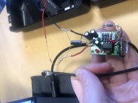
Here's a picture of the setup like @sgrossklass asked for.
So it's a small microphone connected to the amplifier, and the amplifier is also connected to some sort of filter (which I haven't desided yet) which filters from the power bank (which can not be seen in the images) and then connected to a computer through a TRS-cable. That's it!
Not the prettiest setup, but I'm working on it.
Right now I'm still having very high pitch noise, but it sounds much better than without the filter. So at least some progress.
Have a great weekend!
Interesting. That looks like a TLC271 opamp which is a low power low voltage device but it is an unusual device compared to most in that it has a bias setting pin to determine power dissipation and what I'm thinking is that pin may be susceptible to any noise on the rail.
Could it be a path into the device to introduce noise? I don't know as I've never played around with that chip but it is possible.
Could it be a path into the device to introduce noise? I don't know as I've never played around with that chip but it is possible.
I suspect the crux of the matter may be mic bias voltage. The opamp itself isn't so picky, but if that's a typical 2-lead electret capsule, bias voltage needs to be super clean and stable as power supply rejection tends to be on the order of 6 dB only.
It shouldn't be too hard to reverse-engineer that little board (assuming no schematic was supplied) to see where we stand. I imagine the circuitry shouldn't be an awful lot different from something like this or this.
Since the opamp can take supplies of up to +16 V, I might look into adding a little boost converter of the adjustable kind, so you can generate 9-15 V. Even 100 mA of current capability would be plenty. Otherwise I imagine the thing would run absolutely forever on 6-8 AA or AAA cells, especially with a power switch added (idle current probably is <2 mA). There's a reason why these are commonly operated with 9 V block batteries.
BTW, never bend leads directly at an electrolytic cap. This may damage the rubber seal. Use pliers to make bends a few mm out.
BTW, I hope you are aware that the whole setup is tinkerer-grade only and not exactly hi-fi. That little electret capsule alone looks tiny, like 4.something mm. It's the kind of thing you would expect in telephone handsets and headsets.
Good input!
I tried a much lower cut-off frequency than what I had before, and it removed almost everything of the noise.
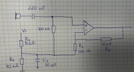
Even though most of the noise is gone, I was thinking about doing some remodeling of the components in amplifier.
Right now it looks like the image that I've attached, but I was thinking about maybe splitting the resistor values that goes to the OP-amp so that I wouldn't amplify as much noise from them.
If I understand it correctly, there is much noise going directly into the OP-amp right now which gets amplified? Anyone who have an idea of how to do this?
Thanks!
I tried a much lower cut-off frequency than what I had before, and it removed almost everything of the noise.
Even though most of the noise is gone, I was thinking about doing some remodeling of the components in amplifier.
Right now it looks like the image that I've attached, but I was thinking about maybe splitting the resistor values that goes to the OP-amp so that I wouldn't amplify as much noise from them.
If I understand it correctly, there is much noise going directly into the OP-amp right now which gets amplified? Anyone who have an idea of how to do this?
Thanks!
Attachments
The virtual ground point should be the signal reference point (meaning the mic ground return should also couple to there) and so is by definition 'clean'. The opamps PSRR (power supply rejection ratio) is really the only way the output can be degraded via noise on the rail. At higher frequencies that will not be great.
- Home
- Amplifiers
- Power Supplies
- Switch mode voltage from power bank, how to filter noise? Use for microphone with amp