Hello everyone,
I will try to make it as concise as i can so let me describe what has happened..
Recently i built 3 Jung superregs. When i plug in the positive one, basically the full input voltage rail appears on output (minus 1V or so). Tried with both +28V-GND and +14v-GND supply. The LED doesnt light up.
This happens on all three boards even though one has 2.5v lm4040 and the other two have Jung's PM829 6.8V reference (which is just two 1N5234B soldered cathode to cathode, and dropped in where the lm329 would go). Opamp used is NE5534 (cheap and pin compatible with ad797, should work at least for testing). This always happens irrespective of R6 (or if it is even present).
The negative side actually regulates something (and the led lights up), but the output is always -6.41v and the 2.5v board is -2.3v (both a bit below their voltage reference somehow, and this is with or without the R13 resistor). Tried with -28V-GND and -15v-GND.
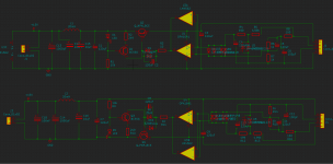
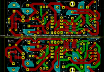
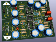
Now, the boards are my own PCB (for personal use) which is more or less the same as diyAudio one, on the v2.3 schematic, with slight alterations (namely : extra footprints for input caps filtering, an input inductor (i tried bridging it and the circuit still behaves the same), and zeners are "doubled up" (meaning one is just an sot-23 footprint, so you install one or the other depending what you have, both are never installed at the same time). Another change is in addition to the single opamps, i added a dual opamp socket as well so one could do both sides with one (as it turns out, doesnt work that way ). I put the screenshots of the schematic and the PCB design in attachment.
The idea in my board was that they're isolated from each other, but have jumper bridges, so you could use it with positive supply but gnd and +v is just flipped on the lower board, so it sees it as negative. And then the double opamp is installed down the middle, one servicing one side and the other side on the other (i think its clearer from the PCB image).
Anyway i quickly abandoned this even though its present on the board. So right now im using them as God (or Jung, or whatever deity) intended, with separate +- DC inputs, and their own single opamps. I forgot to add, transistors are BC560 for pos and BC550 for neg side (instead of 556 and 546).
All three boards exhibit virtually the same behaviour, so its probably not just that i forgot to solder something (unless im a special kind of clumsy and did it three times in a row). Anyway i double checked all the basic stuff and now im scratching my head and writing this post.
If you have any idea what could be going on i would really appreciate it
I will try to make it as concise as i can so let me describe what has happened..
Recently i built 3 Jung superregs. When i plug in the positive one, basically the full input voltage rail appears on output (minus 1V or so). Tried with both +28V-GND and +14v-GND supply. The LED doesnt light up.
This happens on all three boards even though one has 2.5v lm4040 and the other two have Jung's PM829 6.8V reference (which is just two 1N5234B soldered cathode to cathode, and dropped in where the lm329 would go). Opamp used is NE5534 (cheap and pin compatible with ad797, should work at least for testing). This always happens irrespective of R6 (or if it is even present).
The negative side actually regulates something (and the led lights up), but the output is always -6.41v and the 2.5v board is -2.3v (both a bit below their voltage reference somehow, and this is with or without the R13 resistor). Tried with -28V-GND and -15v-GND.
Now, the boards are my own PCB (for personal use) which is more or less the same as diyAudio one, on the v2.3 schematic, with slight alterations (namely : extra footprints for input caps filtering, an input inductor (i tried bridging it and the circuit still behaves the same), and zeners are "doubled up" (meaning one is just an sot-23 footprint, so you install one or the other depending what you have, both are never installed at the same time). Another change is in addition to the single opamps, i added a dual opamp socket as well so one could do both sides with one (as it turns out, doesnt work that way
). I put the screenshots of the schematic and the PCB design in attachment.The idea in my board was that they're isolated from each other, but have jumper bridges, so you could use it with positive supply but gnd and +v is just flipped on the lower board, so it sees it as negative. And then the double opamp is installed down the middle, one servicing one side and the other side on the other (i think its clearer from the PCB image).
Anyway i quickly abandoned this even though its present on the board. So right now im using them as God (or Jung, or whatever deity) intended, with separate +- DC inputs, and their own single opamps. I forgot to add, transistors are BC560 for pos and BC550 for neg side (instead of 556 and 546).
All three boards exhibit virtually the same behaviour, so its probably not just that i forgot to solder something (unless im a special kind of clumsy and did it three times in a row). Anyway i double checked all the basic stuff and now im scratching my head and writing this post.
If you have any idea what could be going on i would really appreciate it
Attachments
I guess you DID think of connecting up the remote sense lines?
Since the LED does not light up, measure the DC across it, and across the 10k in series with it.
Then measure the voltage from the top of the LED to the bottom of the 10k. Then check if the LED is the right way in.
The key here is measuring from input to output until you find what's wrong. Speculation is not very effective ;-)
You can also start at the output: measure the output, then measure the voltages at the opamp input pins, and see if the output of the opamp (which will be max pos) is consistent with the input voltages.
But first get that LED going.
Unfortunately, all that complexity you build in with various parts and various modes don't make it easier.
Jan
Last edited:
I guess you DID think of connecting up the remote sense lines?
Jan
Well, this is embarassing....
Who would have thought that these have a purpose in this life. I was probing without the remote sense lines, since it wasn't hooked up to a load yet ( i was under the impression these only adjusted slightly for the voltage drop of the resistance of the wire or something, so i guess i learned something today).
In retrospect, it makes a lot of sense now why the R6 and R13 didn't even come into play now.
Thank you very much for your help!
EDIT: just so the thread isnt a complete loss, what's the downside of having a very low feedback ratio? I.e why not just always use a 2.5v reference, and have a pot on the R6 and R13 resistors, and get 20+ volts this way? (of course changing the input zener to keep it roughly in the middle).I just built this with a pot and it seems to work fine for now...
Last edited:
It's a thought. It could even be a low value resistor on the output sense, like 100 ohms. The return line would be more problematic; if you would run it like that, performance will suffer.
I prefer that it doesn't work without the connections so it will always work optimally.
Jan
I prefer that it doesn't work without the connections so it will always work optimally.
Jan