The idea started from His Masters Noise phone stage. This make use of a simple and efficient CCS, that is based on two depletion mosfets arranged into a cascode a la Erno Borbely. This work very well !
Later on, I have started to work on Zeno MKII and I ended up with a simple regulator that make use of LT3042. At the hart of LT3042 operation is again a very low noise CCS that feed a resistor. Is a simple and elegant solution to get a low noise reference voltage. Maybe some similar jfet cascoded solution is inside LT304X series.
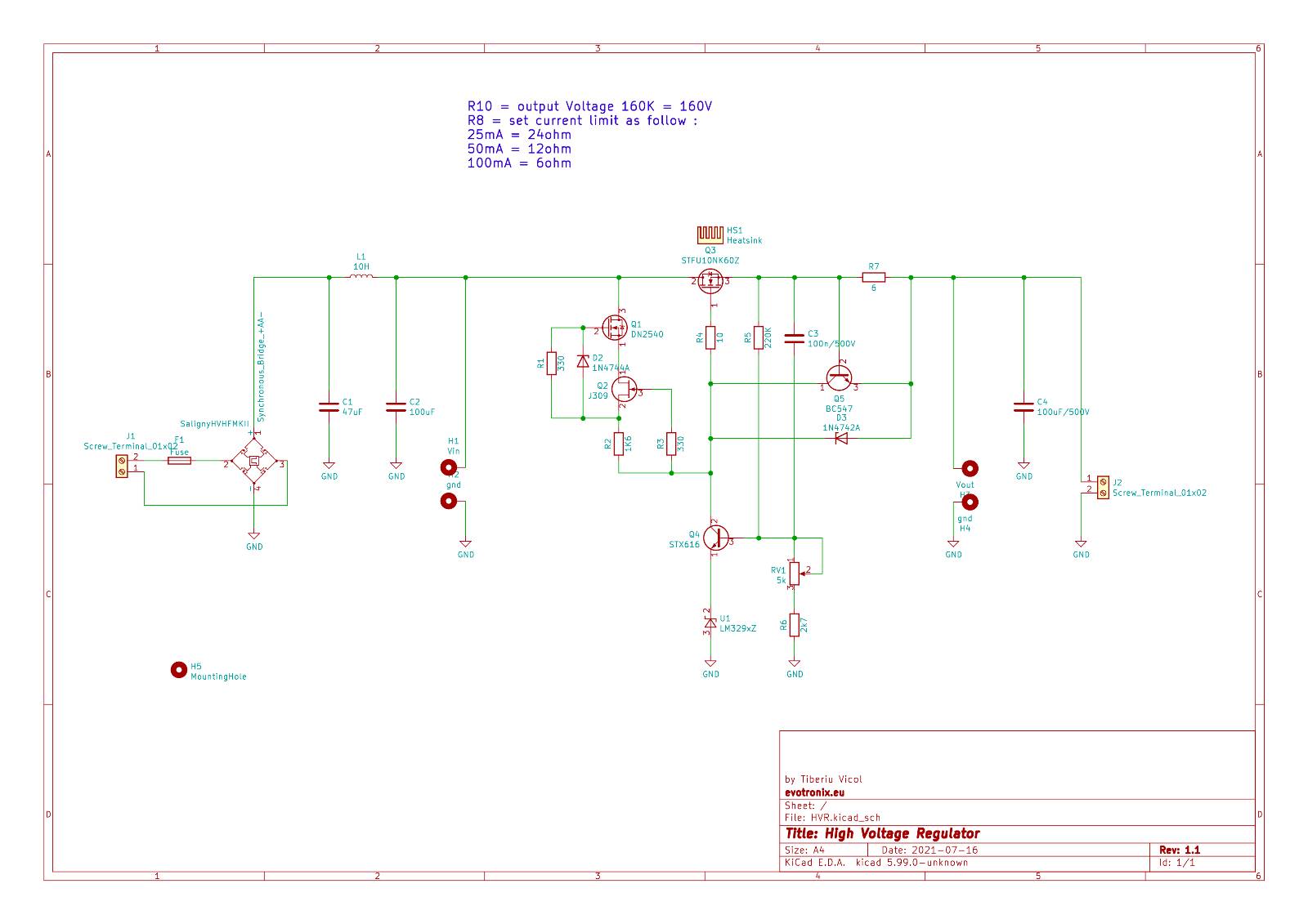
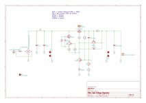
Using the idea from LT3042, with the help of cascoded CCS, a simple, yet reasonable low noise, high voltage, regulator, can be achieved.
Operation is simple. Push constant current into a resistor and you have a voltage reference. Then use a high voltage mosfet to feed some usable current at output.
This is initial idea and it can be extended adding a current limiter for protection. For the time been I'll use a fast fuse.
I plan to pair the regulator with Saligny HVHF and a PCB will follow in KiCAD 5.99 as open-source project.
If you think that R4 is to high and may induce noise, CCS current may be increased from 1mA to 10mA - trough R3, at the cost of power dissipated on R4 resistor and M1. One one hand you reduce resistor noise, but on other hand you increase thermal noise and power dissipated in other parts. For me the "balance" is at 1mA and I'll keep that way.
Choosing a high voltage M1 & M3, this regulator may be also used to regulate very high voltages, maybe over 1kV.
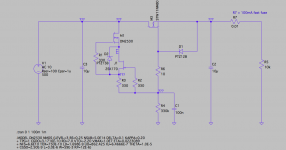
Before going further, here is schematic and Ltspice file. Have a look and let me know your comments/critics.
Regards,
Tibi
KiCad ver.6 source and gerbers at post #20
Latest schematic -> Simple High Voltage Regulator
Later on, I have started to work on Zeno MKII and I ended up with a simple regulator that make use of LT3042. At the hart of LT3042 operation is again a very low noise CCS that feed a resistor. Is a simple and elegant solution to get a low noise reference voltage. Maybe some similar jfet cascoded solution is inside LT304X series.
Using the idea from LT3042, with the help of cascoded CCS, a simple, yet reasonable low noise, high voltage, regulator, can be achieved.
Operation is simple. Push constant current into a resistor and you have a voltage reference. Then use a high voltage mosfet to feed some usable current at output.
This is initial idea and it can be extended adding a current limiter for protection. For the time been I'll use a fast fuse.
I plan to pair the regulator with Saligny HVHF and a PCB will follow in KiCAD 5.99 as open-source project.
If you think that R4 is to high and may induce noise, CCS current may be increased from 1mA to 10mA - trough R3, at the cost of power dissipated on R4 resistor and M1. One one hand you reduce resistor noise, but on other hand you increase thermal noise and power dissipated in other parts. For me the "balance" is at 1mA and I'll keep that way.
Choosing a high voltage M1 & M3, this regulator may be also used to regulate very high voltages, maybe over 1kV.
Before going further, here is schematic and Ltspice file. Have a look and let me know your comments/critics.
Regards,
Tibi
KiCad ver.6 source and gerbers at post #20
Latest schematic -> Simple High Voltage Regulator
Attachments
Last edited by a moderator:
Linear mosfets.
That is a rather good idea in and off itself all trough not new, here is some hopefully constructive criticism mixed in with some offhand remarks, intended to get the ball rolling.
Most switching optimized fets lend themselves poorly to Linear application, but there are specialist devices that have increased DC power handling.
These devices are overkill, because the power dissipated during start-up charging the output cap is no were near enough To induce failure in most cases.
Funnily enough, Ive never seen anyone use IGBT”s for linear applications, Though they have increased SOA compared to mosfets of the same die size.
You could add some form of current limit made out of a MPSA42 and a resistor, But then you run the risk of the mosfet dissipating a lot of power should the load ever draw too much current. but on the other hand, this current limit also limits any surges.
Another nifty additition is a CNY64 optocoupler Whose led is in series over the gate source with a resistor and DO-41 zener in series. this allows you to detect conditions where the mosfet should see too much power, and interface this with digital circuits.
The idea started from His Masters Noise phone stage. This make use of a simple and efficient CCS, that is based on two depletion mosfets arranged into a cascode a la Erno Borbely. This work very well !
Later on, I have started to work on Zeno MKII and I ended up with a simple regulator that make use of LT3042. At the hart of LT3042 operation is again a very low noise CCS that feed a resistor. Is a simple and elegant solution to get a low noise reference voltage. Maybe some similar jfet cascoded solution is inside LT304X series.
Using the idea from LT3042, with the help of cascoded CCS, a simple, yet reasonable low noise, high voltage, regulator, can be achieved.
Operation is simple. Push constant current into a resistor and you have a voltage reference. Then use a high voltage mosfet to feed some usable current at output.
This is initial idea and it can be extended adding a current limiter for protection. For the time been I'll use a fast fuse.
I plan to pair thie regulator with Saligny HVHF and a PCB will follow in KiCAD 5.99 as open-source project.
If you think that R4 is to high and may induce noise, CCS current may be increased from 1mA to 10mA - trough R3, at the cost of power dissipated on R4 resistor and M1. One one hand you reduce resistor noise, but on other hand you increase thermal noise and power dissipated in other parts. For me the "balance" is at 1mA and I'll keep that way.
Choosing a high voltage M1 & M3, this regulator may be also used to regulate very high voltages, maybe over 1kV.
Before going further, here is schematic and Ltspice file. Have a look and let me know your comments/critics.
Regards,
Tibi
I don't think this is a regulator. I think this is a version of a cap multiplier, but I don't see any mechanism to regulate the output.
That may not matter to your application, just wanted to make sure.
Jan
@v4lve lover - thank you for feedback. I'll add some current limiting mechanism.
@Jan - There is no feedback mechanism, so it may no be called "regulator", but neither cap multiplier as long output voltage is kept at desired constant level, like a regulator. :-D
Regards,
Tibi
@Jan - There is no feedback mechanism, so it may no be called "regulator", but neither cap multiplier as long output voltage is kept at desired constant level, like a regulator. :-D
Regards,
Tibi
You have a very nice circuit keep the gate voltage at a constant level. But the source (= output) will vary with load. This is inherent in this kind of circuits and is the limit of what can be done even with an ideal perfect constant gate voltage.
But it can work perfectly in your application.
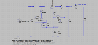
Edit: I modified your .asc to have a variable load, it starts off at 20k and ends at 5k. You can plot V(out) and I(load) and see what's going on.
(I changed the SK170 as it was not in my lib but that doesn't matter here).
Jan
But it can work perfectly in your application.
Edit: I modified your .asc to have a variable load, it starts off at 20k and ends at 5k. You can plot V(out) and I(load) and see what's going on.
(I changed the SK170 as it was not in my lib but that doesn't matter here).
Jan
Attachments
Last edited:
Thank you, Jan !
Design can be further improved, but I want to be simple, very simple. You got the idea and I'm sure you can make it better and this is the reason I'm share here.
This power supply is intended for applications that require low current and operate at relatively constant current, this include tube phono stages, first stage in pre/amplifiers etc.
I have added a current limiter at ~50mA. In the same time I'll keep output fuse at 100mA.
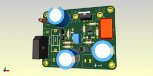
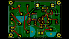
So, here it is in all his glory !
What do you prefer, SMD or THT ? ;-D
Regards,
Tibi
Design can be further improved, but I want to be simple, very simple. You got the idea and I'm sure you can make it better and this is the reason I'm share here.
This power supply is intended for applications that require low current and operate at relatively constant current, this include tube phono stages, first stage in pre/amplifiers etc.
I have added a current limiter at ~50mA. In the same time I'll keep output fuse at 100mA.
So, here it is in all his glory !
What do you prefer, SMD or THT ? ;-D
Regards,
Tibi
Attachments
Yes it is a very useful circuit, and if your load is fairly constant, the output impedance does not matter much. Decoupling the gate is also worth while. It's just that I was confused by the term 'regulator'.
I'm curious why you use the SK170. This is an expensive and rare device whose parameters are not of advantage here. If I had some of those I would save them for my next phono preamp ;-)
Jan
I'm curious why you use the SK170. This is an expensive and rare device whose parameters are not of advantage here. If I had some of those I would save them for my next phono preamp ;-)
Jan
Well, if you have another name that is between cap multiplier and regulator, I'll happy rename it. ")
I have around 300 2SK170BG, 500 2SK170GR and 100 2SK170V/2SJ74V
Few years ago, I have designed a "strange" opamp using these. Maybe, someday, I'll share here.
A wide range of jfet transistors can be used. This design is very flexible and for sure will end up using different parts. I'll add two potentiometers to adjust CCS current and output voltage.
Regards,
Tibi
Well, if you have another name that is between cap multiplier and regulator, I'll happy rename it.
Well, with the gate cap added it works like a cap multiplier. Otherwise, source follower is a correct name as well.
I have around 300 2SK170BG, 500 2SK170GR and 100 2SK170V/2SJ74V
You're sitting on a gold mine!
I would also use SMD when possible. Compact layout, less stray cap and inductance.
Jan
Yes, nice circuit. One tip: if you pre-bias U1 with a small current from the output, its voltage will depend less on the transistor emitter current, and thus will be more stable, improving regulation.
Also, the 10H inductor is probably a typo; I don't think you can cram 10H in such a small inductor. Maybe you meant 10mH? Even that will be hard to find.
Jan
Also, the 10H inductor is probably a typo; I don't think you can cram 10H in such a small inductor. Maybe you meant 10mH? Even that will be hard to find.
Jan
Hi Tibi, I'm following this project with interest.
Just a couple of questions:
- what would be the minimum (or the optimal, if any) voltage drop for this regulator?
- what would be the maximum input and output voltage allowed with the PCB you are designing?
And a couple of suggestions:
- regarding the 10H filter "inductor", it would be nice if the PCB hole spacing could accomodate the Tent/Vanderveen Mini-Electronic Chokes (MEC-100, MEC-200). I tried them and found they work fine.
- if the output current could be stretched to, say, 120-130mA the regulator would also be usable for some small power amp (thinking to PP 2A3/300B, with CCS on cathodes, tubes polarized at around 60mA per tube).
Thank you,
Fausto
Hi Fausto,
Minimum voltage drop will be around 20V. Optimum voltage drop around 50V. Maximum voltage drop around 100V.
Currently PCB was designed with a clearance of 1,5mm. This will be increased later to 2.5mm to allow 500Vdc operation.
Thanks for the suggestion with Tent/Vanderveen E-Choke. I'll adapt board to allow this.
Depending on the power dissipated over the mosfet, output current can be increased vell above 100mA. For this you need to mount mosfet on a separate heatsink.
For the time been, here are the gerbers for this design.
Regards,
Tibi
Attachments
I don't think this is a regulator. I think this is a version of a cap multiplier, but I don't see any mechanism to regulate the output.
That may not matter to your application, just wanted to make sure.
Jan
In the original circuit, there is the 100 % local voltage feedback in the source follower: when the output voltage gets too high, the gate-source voltage drops and reduces the current. I think the original circuit is a series regulator, albeit not a very good one (which may or may not matter depending on the application).
E-Choke was included.
Attached source kicad project. Please note that you must use nightly 5.99 to open files.
hvr.zip contain gerbers for production.
Enjoy !
Regards,
Tibi
Attached source kicad project. Please note that you must use nightly 5.99 to open files.
hvr.zip contain gerbers for production.
Enjoy !
Regards,
Tibi
Attachments
- Home
- Amplifiers
- Power Supplies
- Simple High Voltage Regulator