
I understand.
I will make the recommended change.
EDIT.
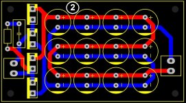
About this way, if I understood correctly?
Better! I would place the connectors in the middle for better looks. Also I would use either CRC or CLC with fewer but larger value caps. Plated through mounting holes would make it a sturdy board.
A power LED and series resistor would serve 2 purposes: visual indication that the device is powered on and the LED would discharge the caps at power off also when there would be little to no load.
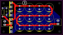
Now ... if the board will be used for a device where an extra regulated PSU is needed (relays, digital volume control, muting relay..) then a small regulator could be added. If the board would be used for a source device of sorts then a main regulator could also be added, preferably a modern low noise LDO regulator to keep heat and energy wasting as low as possible.
Last edited:
Generally we use a square pad for the + terminals, and a round pad for the negative terminals,
for electrolytic capacitors. This helps to avoid mistakes when stuffing the board.
For diodes, the + anode has a square pad, and the - cathode has a round pad.
Check the bottoms of the snap-in capacitors. Sometimes there is a large flat contact next to the lead.
This can touch a nearby trace and cause a short, either immediately or after some time
rubbing on the solder mask.
Also the square pad is good to use for pin #1 of a terminal block.
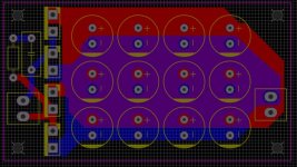
True but... modern PCB material is not as good as it used to be (sorry but most material is just barely acceptable) and square pads are the pads that peel off most easy. Nowadays I avoid square pads for that reason.
Your remark on snap in caps triggered me. It is nearly always so that snap in caps have better specifications than their normal radial cousins, it is advisable to use snap in caps.
Your remark on snap in caps triggered me. It is nearly always so that snap in caps have better specifications than their normal radial cousins, it is advisable to use snap in caps.
Last edited:
For now, it's just a sketch, I leave the details like this at the end.Generally we use a square pad for the + terminals, and a round pad for the negative terminals,
for electrolytic capacitors....
Now ... if the board will be used for a device where an extra regulated PSU is needed (relays, digital volume control, muting relay..) then a small regulator could be added. If the board would be used for a source device of sorts then a main regulator could also be added, preferably a modern low noise LDO regulator to keep heat and energy wasting as low as possible.
I thought of using zenner and a capacity multiplier. If there are other better solutions, I will adopt them.
Last edited:
I thought of using a Zener diode and a capacity multiplier. If there are other better solutions, I will adopt them.
What is the load? It really helps if the OP gives enough information. Suppose you are in a restaurant in a country far away and you ask the waiter for advice what to order of the local dishes. He then asks what you like and you say you don't know
")
Last edited:
But I don't see a reason to use such a large amount of el. caps at all.
Because I have many pieces of 470uF / 1000uF at 35-50 volts.
It is a habit amongst DIYers and it is hard to get rid of but designs are best designed with optimally chosen parts instead of using what is in stock...
This means keeping no stock is both economical, less space occupying and performance improving. BTW you haven't replied what the purpose of the PSU is.
This means keeping no stock is both economical, less space occupying and performance improving. BTW you haven't replied what the purpose of the PSU is.
Last edited:
Sorry.What is the load?
I'm going to use the source for headphone amplifiers. So something between 200mA and 800mA.
Then CLC is a choice and a low noise low drop out regulator seems mandatory. With such a load it is advisable to include a well chosen low noise LDO regulator and to include a heatsink on the board. Make it a habit to include mounting holes near that heatsink to improve cooling. The same holes as the plated through mounting holes are adequate.
I designed this simple device years ago and it was apparently tested. Despite its simplicity every part was chosen with care for optimal performance. Excuse me for shameless self promotion but here is the link, maybe you get inspiration:
https://www.diyaudio.com/forums/power-supplies/371849-power-supply-tests-archives.html#post6642040
Last edited:
Good question! I unpolitely return the question. What would you at least try to cut off? Hint: take size, current rating, price into account as well.
You can add several but also note the specifications of the regulator and keep the law of diminishing returns in mind.
You can add several but also note the specifications of the regulator and keep the law of diminishing returns in mind.
Last edited:
Thanks Michael but I'm using Win7. I hope it works properly.
Jean-Paul
My English is gone ... I'm afraid I didn't understand very well.
In most projects the problem was those 100 Hz. Not always but quite often.
And not just 100Hz. Sometimes even more, especially using LM317, to give an example.
Jean-Paul
My English is gone ... I'm afraid I didn't understand very well.
In most projects the problem was those 100 Hz. Not always but quite often.
And not just 100Hz. Sometimes even more, especially using LM317, to give an example.
- Home
- Amplifiers
- Power Supplies
- Capacitor connection. Beginner question ...