Hey everyone,
New member here, hope this is the appropriate forum to post this. I made sure to search first, but didn't find any topics pertaining to my issue.
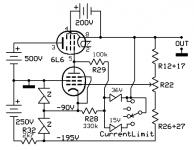
I recently built Pete Millett's hv bench power supply ( High-voltage bench supply ) and am having some trouble getting B+ voltage. I have filament voltage and negative bias voltage, but had -
6v on the B+ out. After tracing my work and comparing it to the schematic a few times, I'm 99% sure that my wiring is correct.
I contacted Mr. Millett directly for advice on what I may have done wrong. He responded promptly and told me that he didn't see how the circuit could work as drawn, as the error amp plate (V5 pin 7) should be connected to B+. He suggested I connect the 330k resistor in the schematic at the current limit circuit from pin 7 to B+. This gave me +.4v and some current meter swing when playing with the 100k pot, but nothing more. Unfortunately, he said he may have found the problem after he uploaded the pictures to the web page and corrected it later, however that was 15 years ago and he no longer has the unit.
I'm curious if anyone here has built this supply and run into a similar problem? How did you correct it? I'm learning tube circuit design, but I am in no way experienced enough at the moment to figure out why this supply isn't working without help, so if anyone has any ideas on what could cause my issue (assuming it is a design flaw and not just a wiring error on my part), would anyone be willing to take a look at the schematic in the link above and make any suggestions? I spent months building this and I'm not quite ready to give up on it, but I'll admit I'm getting close.
Thanks for any help everyone,
Daniel
New member here, hope this is the appropriate forum to post this. I made sure to search first, but didn't find any topics pertaining to my issue.
I recently built Pete Millett's hv bench power supply ( High-voltage bench supply ) and am having some trouble getting B+ voltage. I have filament voltage and negative bias voltage, but had -
6v on the B+ out. After tracing my work and comparing it to the schematic a few times, I'm 99% sure that my wiring is correct.
I contacted Mr. Millett directly for advice on what I may have done wrong. He responded promptly and told me that he didn't see how the circuit could work as drawn, as the error amp plate (V5 pin 7) should be connected to B+. He suggested I connect the 330k resistor in the schematic at the current limit circuit from pin 7 to B+. This gave me +.4v and some current meter swing when playing with the 100k pot, but nothing more. Unfortunately, he said he may have found the problem after he uploaded the pictures to the web page and corrected it later, however that was 15 years ago and he no longer has the unit.
I'm curious if anyone here has built this supply and run into a similar problem? How did you correct it? I'm learning tube circuit design, but I am in no way experienced enough at the moment to figure out why this supply isn't working without help, so if anyone has any ideas on what could cause my issue (assuming it is a design flaw and not just a wiring error on my part), would anyone be willing to take a look at the schematic in the link above and make any suggestions? I spent months building this and I'm not quite ready to give up on it, but I'll admit I'm getting close.
Thanks for any help everyone,
Daniel
You could start be checking the error amp operation (V7).
Check the Vgk of that tube, does it 'see' the problem, is it trying to drive the output tubes further open?
The other thing is that the anode voltage of V7 depends on the output, so you have a chicken and egg situation here. V7 should have an anode voltage independent of the output B+.
Connect that 330k (R28?) to a stable high voltage point like RAW_B+. That could fix it right there.
Jan
Last edited:
You got no water in the bathroom. (Or the tap sucks air.) How do you find the problem? Usually some variation of testing for water at accessible points from bathroom tap back to the lake/well. Open the tap in the kitchen, the garden.
You don't need a PhD in hydrology to know water should come out of most places in plumbing.
Here you should have big AC at T1, big DC after rectifiers D1 to D8, through the chokes to the big tubes.
You don't need a PhD in hydrology to know water should come out of most places in plumbing.
Here you should have big AC at T1, big DC after rectifiers D1 to D8, through the chokes to the big tubes.
told me that he didn't see how the circuit could work as drawn, as the error amp plate (V5 pin 7) should be connected to B+. He suggested I connect the 330k resistor in the schematic at the current limit circuit from pin 7 to B+.
Daniel
Missed this the first time but it is what I mentioned in post # 2. If you connect the 330k to RAW_B+ instead of the (output) B+, I bet you're in business.
Pete might have meant that.
Jan
Agreed, connecting it to B+ is not the solution, because it creates a chicken and egg situation. It can not work unless B+ comes up, and B+ doesn't come up unless it works.
He should connect it to RAW_B+ which is available as a plate supply independent from the output B+.
Jan
He should connect it to RAW_B+ which is available as a plate supply independent from the output B+.
Jan
Tubes are depletion mode devises, no start-up problem.
The R28 (330k) provide a bias current for the current limit zeners.
With the output to low the control tube is blocked and the Vg1k of the pass tube is equal to the selected zener.
Depending on the load on the output the voltage goes up until the current is the maximum possible with the chosen -Vg1k. If the output voltage try to go to high the control tube wakes up and start pulling the g1 of the pass tube down.
Now with R28 to a positive voltage, all zeners give a +0,6V = Vg1k at start-up and the pass tube will allways pull with maximum possible current on the load.
So again, is the 200V present on the pass tubes screens ?
Mona
Hello everyone,
thank you for he replies! I made the original post while at work on a short break, so I was in a hurry and realized I forgot a couple details.
First thing I forgot to mention is that I do have all voltages present. I have 500v raw B+ to the plates of the pass tubes, 250v on the screen supply (which is actually high, schematic says 200v), I have -90 at pin 2 and 5 of V8 and V6 which is also what I measured on the cathode of V5. I also have the -195v for bias.
Next thing these voltages are on the correct pins on the pass tubes, however I didn't use 807s. Pete said the circuit would work with 6L6 tubes, so I used 6N3C tubes, a Russian equivalent to the 6L6. Not sure if this could impose a problem. It goes without saying that I did use the correct pins and I'm only mentioning that to eliminate wiring of the pass tubes as being an issue.
As far as the 330K to raw B+, I tried disconnecting the 330K on the schematic, as its soldered to a board, and adding one that just went from V5 pin 7 to a node right after the four 470uf capacitors on the B+ supply, basically where R2 is on the B+. Did I do the right thing? This is what gave me my change from -.6V to +.4v and some current meter swing when fiddling with the 100K pot, but no real voltage swing or voltage at all. On the Heathkit IP-17 schematic, the unit Pete "loosely" based this schematic off of, the control amplifier plate connects to the control grids through two 1k ohm resistors and to B+ on the cathode side of the pass tubes through a 470K ohm resistor.
Beyond that change, should I change anything else around the error amp? The only other tube device I built was a single tube radio in the shape of a DNA strand for a high school project, a far cry from what this thing is. That was around 15 years ago. In other words, I'm inexperienced as a builder and designer, so my apologies if it seems I need a little hand holding lol.
Thank you again everyone, your help is invaluable to me.
Daniel
... I didn't use 807s. ...6L6 ...I used 6N3C tubes ....
It goes without saying that I did use the correct pins....
I'm inexperienced as a builder...
Hm.
Ketje, you suggest to connect the V7 load resistor (330k) to the output B+. Would that still work if the B+ is set to say 25V??
My suggestion is to connect the 330k to RAW_B+. I still am convinced that this single change will fix all the problems, which really is only ONE problem: anode voltage for V7.
Assuming of course no other mistakes were made...
Jan
My suggestion is to connect the 330k to RAW_B+. I still am convinced that this single change will fix all the problems, which really is only ONE problem: anode voltage for V7.
Assuming of course no other mistakes were made...
Jan
As I wrote before, connecting the 330k to a positive voltage is no good idea.The zeners in the current limit get biased in the wrong way.
There is no need for a positive voltage.
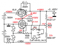
Only the values of R12 and R27 are odd, not the values to get 0...400V out with the 100k potmeter.
Here the voltages I expect in respect to the cathode of the control tube.
Mona
There is no need for a positive voltage.
Only the values of R12 and R27 are odd, not the values to get 0...400V out with the 100k potmeter.
Here the voltages I expect in respect to the cathode of the control tube.
Mona
Attachments
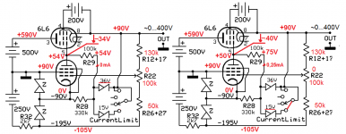
With the 36V zener for the max current limit there is a problem, there isn't enough negative voltage to block the pass tube(s).Yes but how does that look when B+ is dialed down to 0V?
With the 15V limiter all is well if there is enough load.
If there isn't the circuit fails and the output remains to high.
Problems of a circuit with an active pull-up and a passive pull-down.
Mona
Attachments
Just a quick response until I can continue investigating the circuit with your suggestions.
Jan, I already connected the 330k to RAW B+. This did not work. I have been reading what you post, I think there was a misunderstanding.
Hello Mona, I will check D17 and make sure I didn't put it in backwards. It's absolutely possible. Likely won't be able to check until Saturday, but I will get back to you by then.
Pins 2 and 7 are connected as heaters. Pin 8 is cathode and has the 10 ohm resistor tied to pin 2, filament. Pin 5, control grid, 1k resistor to pin 7 error amp. Pin 4 to 150 ohm resistor to screen supply. Is this incorrect? This is how I read the schematic. The "goes without saying" wasn't intended to be arrogant, I just made sure to not wire it like an 807.
Daniel
Ketje, I don't think he reads what we post ...
Jan
Jan, I already connected the 330k to RAW B+. This did not work. I have been reading what you post, I think there was a misunderstanding.
He checked the Vg2 so I think he does.
Looks like the pass tubes are doing nothing, if it's not Vg2 then are heaters on ?
Or a allmost short circuit at the output, D17 (1N4007) in the right direction ?
Mona
Hello Mona, I will check D17 and make sure I didn't put it in backwards. It's absolutely possible. Likely won't be able to check until Saturday, but I will get back to you by then.
Pins 2 and 7 are connected as heaters. Pin 8 is cathode and has the 10 ohm resistor tied to pin 2, filament. Pin 5, control grid, 1k resistor to pin 7 error amp. Pin 4 to 150 ohm resistor to screen supply. Is this incorrect? This is how I read the schematic. The "goes without saying" wasn't intended to be arrogant, I just made sure to not wire it like an 807.
Daniel
- Status
- This old topic is closed. If you want to reopen this topic, contact a moderator using the "Report Post" button.
- Home
- Amplifiers
- Power Supplies
- Pete Millett High Voltage Power Supply- Need help