Features:
- 270VA Toroid
- 60Hz line
- Output from 1 to 30v with maximum current of 7A
- adjustable current control
- use of the LM723
- filter capacitors: 4700uf and 22000uf
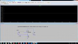
I imagine a single Mosfet, using its Rds resistance as an integral part of the CRC filter and as a shunt resistor for reading current. Also using as a soft partial start.
Well, for a cut frequency of 50Hz, the calculated resistance was 0.14R. I have the IRF6218 which has the Rs = 0.15R.
What are the possible problems that I will face with this configuration?

Update #16

Update #32

Update #41

- 270VA Toroid
- 60Hz line
- Output from 1 to 30v with maximum current of 7A
- adjustable current control
- use of the LM723
- filter capacitors: 4700uf and 22000uf
I imagine a single Mosfet, using its Rds resistance as an integral part of the CRC filter and as a shunt resistor for reading current. Also using as a soft partial start.
Well, for a cut frequency of 50Hz, the calculated resistance was 0.14R. I have the IRF6218 which has the Rs = 0.15R.
What are the possible problems that I will face with this configuration?
Update #16
Update #32
Update #41
Last edited:
RSdon is highly temperature dependant, and less linear than a resistor.
You are on to something though, if you keep the idea of using the Rsdon in mind for later reference, you may thank yourself later.
For example, if you use a mosfet as a switch, you can detect that the mosfet has gone out of saturation by measuring the voltage over drain-source
You are on to something though, if you keep the idea of using the Rsdon in mind for later reference, you may thank yourself later.
For example, if you use a mosfet as a switch, you can detect that the mosfet has gone out of saturation by measuring the voltage over drain-source
Hi, basreflex!
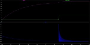
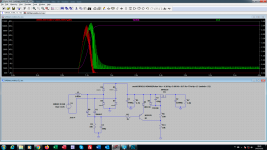
The capacitor at the base of transistor Q1 will raise the VBE gradually. VCE will gradually reduce, decreasing the gate value. The Rds resistance of the Mosfet will also gradually decline, until it reaches the value of 0.15R. Notice in the image, the peak current over the 22,000uf capacitor rising smoothly. Peak current of 3A here in my simulator. The simulator has a peak current of 50A, without the Mosfet.

The capacitor at the base of transistor Q1 will raise the VBE gradually. VCE will gradually reduce, decreasing the gate value. The Rds resistance of the Mosfet will also gradually decline, until it reaches the value of 0.15R. Notice in the image, the peak current over the 22,000uf capacitor rising smoothly. Peak current of 3A here in my simulator. The simulator has a peak current of 50A, without the Mosfet.
using the fet to dissipate the voltage difference while charging the large cap is a bad idea.
the fet does not really softstart in my sim. the 22mf cap simply shorts the transformer and the fet sees a peak power of 500W during 10msec. the 1.8 ohms load resistor in your schematic looks a bit strange, normally a supply starts unloaded.
the fet does not really softstart in my sim. the 22mf cap simply shorts the transformer and the fet sees a peak power of 500W during 10msec. the 1.8 ohms load resistor in your schematic looks a bit strange, normally a supply starts unloaded.
if you charge a cap with a resistor or switch, assuming an ideal voltage source, that is done with 50% efficiency. so the same of the energy that the cap contains is lost in the switch.
for a 22mF 40V cap, hou are puttin 17.6J in the fet . in practice the diode bridge, and transformer take part of that loss.
for a 22mF 40V cap, hou are puttin 17.6J in the fet . in practice the diode bridge, and transformer take part of that loss.
my RC values are 470k//1M and 10u, corresponding to approx 50msec delay, but the switching on of the fet is still very abrubt given the high voltage gain of the bipolar transistor. quick estimate: 40 times the voltage across the collector resistor or 1000x. (40 stems from the inverse of QU/kt or 25mV). so whatever small base rise at the bipolar you get, it gets amplified heavily into a quick rise gate voltage. so it's delay only , not soft. better use 2 fets, a smaller to switch a resistor, and a big delayed one for normal operation. or a simple resitor across the big fet, and switch the fet based on its D-S voltage, instead of time delay.
softstart with R and fet
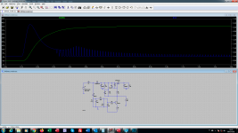
a sim with the resistor and fet is here , soft charge the 22mF cap and short the resistor at 3.2sec. the decision to turn on the fet is based on its D-S voltage, roughly at the Vt of a BSS84. the current looks oscilatory, but is just the 100Hz current spikes of the rectified sine.
a sim with the resistor and fet is here , soft charge the 22mF cap and short the resistor at 3.2sec. the decision to turn on the fet is based on its D-S voltage, roughly at the Vt of a BSS84. the current looks oscilatory, but is just the 100Hz current spikes of the rectified sine.
Attachments
Basreflex
You could check if I'm commenting on any major mistakes again. First time I use this simulator.
The idea here is to keep the Mosfet in the resistive area. The time determined by the transistor.
You could check if I'm commenting on any major mistakes again. First time I use this simulator.
The idea here is to keep the Mosfet in the resistive area. The time determined by the transistor.
Attachments
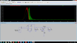
by inspecting the current in R5 you will see that the Q1 is starting to conduct at t=0.5sec. the fet is turned on by R11, slowed down by C6. as the voltage on C1 drops, the gate drive on M1 drops such that a soft turn on results. still the fet peak power (plot using CTRL+ALT over the part ) 180W, 11J total. the transformer does not like halfwave rectification, but I guess that for sim simplicity. Q1 is not bringing in anything into the circuit.
Loading in 1.2 seconds. The IRF6218 will do well with this peak current/power.
I now need to simulate the "off/on" behavior. I suspect that C5 can keep the mosfet switched on in the low resistance area, with C2 heavily discharged. I need to check the "off/on" behavior but I still don't know how to configure the simulator.
I now need to simulate the "off/on" behavior. I suspect that C5 can keep the mosfet switched on in the low resistance area, with C2 heavily discharged. I need to check the "off/on" behavior but I still don't know how to configure the simulator.
Attachments
on-off
here is an example.
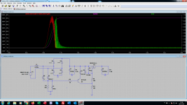
when power fails, the M2 is quickly turned off, and M3 turns off allowing the PNP bipolar to discharge C5.
using a PNP does not have to use fet gate zeners. M3 needs to be a fet with 20V gate capacbility. R5, R6 make that the gate voltage does not exceed that.
here is an example.
when power fails, the M2 is quickly turned off, and M3 turns off allowing the PNP bipolar to discharge C5.
using a PNP does not have to use fet gate zeners. M3 needs to be a fet with 20V gate capacbility. R5, R6 make that the gate voltage does not exceed that.
Attachments
basreflex,
your help has been very important for my learning. Your ideas are very good! I will test your circuit in practice.
Taking a ride on your solution, I designed a more simplified circuit, using only the PNP transistor and it is working well in the simulator.
your help has been very important for my learning. Your ideas are very good! I will test your circuit in practice.
Taking a ride on your solution, I designed a more simplified circuit, using only the PNP transistor and it is working well in the simulator.
Attachments
i like your simple solution. D4 has 2 purposes, the unexpected one is to protect the PNP, when someone accidentially shorts C1, the BE diode breaks through in reverse mode. D4 prevents that. a small divider by adding a resistor from the base of Q1 to the C1/plus does also help to reduce inadvertent turn-on of the PNP. and lower cost diodes can be used instead of schottky's.
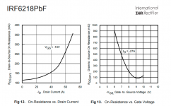
With the objective of improving the result of my simulation, I decided to seek information on the characteristics of the IRF6218, for mounting the VDMOS. In this link below the International Rectifier, I obtained the necessary information for the 6218.
Spice Model Links, Saber Model Links and Library File links for Google Index and those who find them.
The VDMOS was assembled with the following values:
.model IRF6218 VDMOS(Pchan Vto=-4.28 Rg=3.88 Rd=1e-6 Rs=72m Kp=7.77 Lambda=.22)
With the circuit shown, I am getting a Rdson = 0.1R, where it should approach 0.15R.
As a parameter, I decided to test it with the IRF9240, which is in the LtSpice list. The value of Rdson should be close to 0.5R but to my surprise it is 0.27R. Is this right ? Where am I going wrong?
Attachments
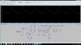
Small adjustments in the VDMOS of the IRF6218 brought a better approximation of the "Rds (on) x ID," according to the datasheet graph.
.model IRF6218 VDMOS(Pchan Vto=-4.28 Rg=3.88 Rd=.017 Rs=77m Kp=15 Lambda=.52)
As shown in the graph, satisfactory ripple voltage at maximum current (7A). CRC filter working as expected.
1- Soft start - OK
2- CRC filter - OK
3 - i-sense - Waiting for my MAX4080 order
.model IRF6218 VDMOS(Pchan Vto=-4.28 Rg=3.88 Rd=.017 Rs=77m Kp=15 Lambda=.52)
As shown in the graph, satisfactory ripple voltage at maximum current (7A). CRC filter working as expected.
1- Soft start - OK
2- CRC filter - OK
3 - i-sense - Waiting for my MAX4080 order
Attachments
Last edited:
using the fet to dissipate the voltage difference while charging the large cap is a bad idea.
the fet does not really softstart in my sim. the 22mf cap simply shorts the transformer and the fet sees a peak power of 500W during 10msec. the 1.8 ohms load resistor in your schematic looks a bit strange, normally a supply starts unloaded.
I've also explored this modelling - 6mF with a various ways to attempt to limit the incoming inrush, in the end it's probably better to ensure the output is muted and then simply PWM the inrush at high frequency. The only issue is the noise and switching will go back to the transformer.
You can get 500W resistors, metal clad with leads - they'll cope with the inrush to a point. I tried 4 or 5 resistance steps that bypassed in sequence but you still get an inrush.
- Home
- Amplifiers
- Power Supplies
- Three functions for a Mosfet: CRC Filter, Soft Start and i-sense. Will it work or not