Proceeding with final tests:
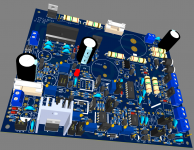
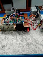
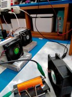
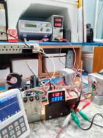
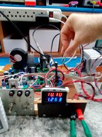
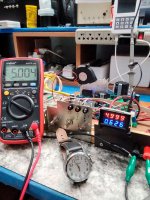
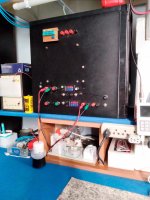
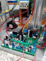
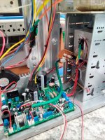
image 1 - The LM723 (ST) is presenting itself with very good stability. Results well above my expectations.
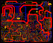
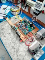
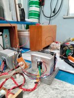
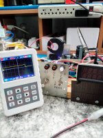
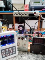
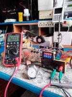
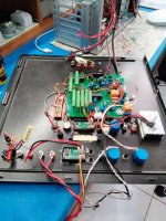
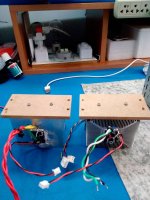
image 2- Due to my need to use a relatively long cabling, I decided to group the components of the sziklai structure on the heatsink. I kept the cabling well braided and so far, it has good stability.
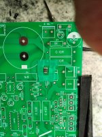
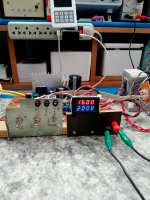
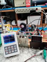
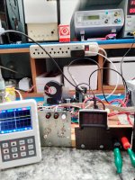
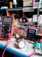
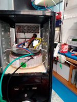
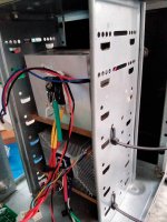
image 3 - fans operating with heatsinks at 50ºc.
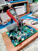
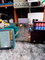
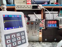
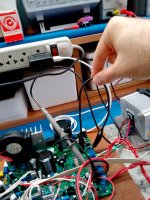
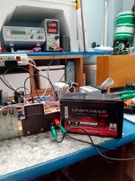
image 4 - I turned off the fan to test the temperature protection. I set the OTP to 60ºc and it worked as scheduled.
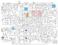
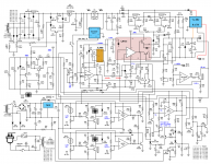
image 5 - new schematic update.
image 1 - The LM723 (ST) is presenting itself with very good stability. Results well above my expectations.
image 2- Due to my need to use a relatively long cabling, I decided to group the components of the sziklai structure on the heatsink. I kept the cabling well braided and so far, it has good stability.
image 3 - fans operating with heatsinks at 50ºc.
image 4 - I turned off the fan to test the temperature protection. I set the OTP to 60ºc and it worked as scheduled.
image 5 - new schematic update.
Attachments
Testing the OVP.
Image 1: PSU set at 10v, with a load of 1.25A. Using external PSU, to force the output voltage to be raised (image 2). Image 3 shows the OVP in action (adjusted around 10% overvoltage tolerance).
Image 4: PSU will be energized, being in a short circuit the power transistors. When energizing the PSU (image 5) the OVP acts immediately, without any trace of voltage at the output.
Image 6: PSU at 10v, with a load of 1.25A. Closing a short circuit between collector and emitter of the power transistors, throwing the 40v at the output. Observe the rapid action of the OVP on the oscilloscope (image 7). I don't know if it's fast enough (40A inrush) to save a more sesible DUT. Anyway, you have scope to change the SCR, as well as lower the resistance values even more.
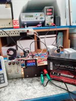
Image 8: PSU charging a battery. Image 9 shows the PSU being turned off, with the battery connected to the terminals. Image 10 shows the PSU being turned back on, with the OVP detecting the battery and keeping the PSU in cut until the battery is removed. Image 11 shows the PSU turning on normally, after removing the battery.
Image 1: PSU set at 10v, with a load of 1.25A. Using external PSU, to force the output voltage to be raised (image 2). Image 3 shows the OVP in action (adjusted around 10% overvoltage tolerance).
Image 4: PSU will be energized, being in a short circuit the power transistors. When energizing the PSU (image 5) the OVP acts immediately, without any trace of voltage at the output.
Image 6: PSU at 10v, with a load of 1.25A. Closing a short circuit between collector and emitter of the power transistors, throwing the 40v at the output. Observe the rapid action of the OVP on the oscilloscope (image 7). I don't know if it's fast enough (40A inrush) to save a more sesible DUT. Anyway, you have scope to change the SCR, as well as lower the resistance values even more.
Image 8: PSU charging a battery. Image 9 shows the PSU being turned off, with the battery connected to the terminals. Image 10 shows the PSU being turned back on, with the OVP detecting the battery and keeping the PSU in cut until the battery is removed. Image 11 shows the PSU turning on normally, after removing the battery.
Attachments
-
 ovp_10v.jpg808.1 KB · Views: 61
 -
 ovp_11_18v.jpg578.2 KB · Views: 46
 -
 ovp_start_11.jpg607.5 KB · Views: 56
 -
 ovp_start_psu_short.jpg618 KB · Views: 43
 -
 ovp_start_short.jpg623 KB · Views: 45
 -
 ovp_short_CE.jpg645.8 KB · Views: 44
 -
 ovp_start_short_CE.jpg606.6 KB · Views: 50
 -
 ovp_lb_on_psu.jpg619.9 KB · Views: 53
 -
 ovp_lb_off_psu.jpg612.1 KB · Views: 49
 -
 ovp_lb.jpg639.1 KB · Views: 40
Continuing the tests:
image 1: Mosfet acting on Soft Start, taking 200ms to charge the 22mf capacitor.
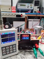
Images 2, 3 and 4: Checking the output voltage within 5 hours, showing a good precision, above my expectations.
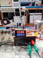
Image 5: 0.34v is the minimum possible value for the output voltage.
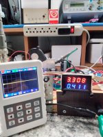
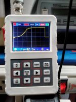
image 6: Output voltage at 3.3v. Oscilloscope on the 50mv scale, without showing signs of significant noise.
image 7: Output voltage at 12v. Oscilloscope on the 50mv scale, without presenting significant noise.
image 1: Mosfet acting on Soft Start, taking 200ms to charge the 22mf capacitor.
Images 2, 3 and 4: Checking the output voltage within 5 hours, showing a good precision, above my expectations.
Image 5: 0.34v is the minimum possible value for the output voltage.
image 6: Output voltage at 3.3v. Oscilloscope on the 50mv scale, without showing signs of significant noise.
image 7: Output voltage at 12v. Oscilloscope on the 50mv scale, without presenting significant noise.
Attachments
Project completed.
Attachments
Hi
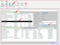
I needed to carry out a cost assessment for this project. I updated my inventory control to get a cost report. You can download my app which is free.
A small (open source) Inventory Control application using Ms Access. - Page 1
I needed to carry out a cost assessment for this project. I updated my inventory control to get a cost report. You can download my app which is free.
A small (open source) Inventory Control application using Ms Access. - Page 1
Attachments


- Home
- Amplifiers
- Power Supplies
- Three functions for a Mosfet: CRC Filter, Soft Start and i-sense. Will it work or not