24V dc to 300V dc capacitor charger with regulation (300V at 150mA at 78% efficiency): https://www.analog.com/media/en/technical-documentation/data-sheets/lt3751.pdf
So this not only can cope with managing inrush on a 2+mF 300V cap, it can also then regulate current output too. User configurable max charging limit too..
Seems it may be of interest to tube users.. now if only there was a larger regulated 500mA-1A version.
There’s also a coilcraft transformer specifically for this..
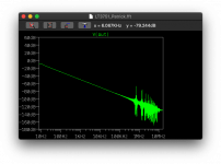
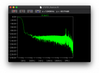
Actually with 150mA you could make all the 6SN7+6AS7 single tube amps.. one per channel and you're laughing. 6mF + 5.1R resistor then 1.5mF and 2K and you've got a -90dB at 100Hz second order passive filter. Probably the quietest bottle head amp out driven by a SMPS. (would need to check the cap high frequency responses before claiming that though).
The LT3750 is essentially the non-regulating version of this and works on 6-24V, there's no feedback from the secondary side of the transformer. I thought about using this as an initial charge up of the system before switching out for a larger standard switched mode power supply where it wouldn't see the pre-charged caps as a short.
The LT3750 is essentially the non-regulating version of this and works on 6-24V, there's no feedback from the secondary side of the transformer. I thought about using this as an initial charge up of the system before switching out for a larger standard switched mode power supply where it wouldn't see the pre-charged caps as a short.
Last edited:
I found this thread on the subject previously but I don't think it goes into much more than using it as standard 400V: LT3751 Driven, +/-400V Shunt Regulated Supply
Actually using a Coilcraft 3460-BL that's 50A output 12-24V input and 500V out: GA3460-BL | Coilcraft
So theoretical max of 600VA (50A*12V) now that means you can change switching fet in parallel. I missed the examples on the phone this morning: https://www.analog.com/media/en/technical-documentation/data-sheets/LT3751.pdf A number of ideas - including a 42A capacitor charger (12V in and HV out), a 100-400vdc in 100-400vdc out etc etc.
The interesting bit for me is that it could provide the power I need albeit with a 20Vripple as documented in the thread above. Not a problem if you have output available only issue is how much current secondary side do I have to play with.
So a 500W 12-24V supply, a current limiting and capacitor short aware step system like this, and it could be two steps with a capacitor to give a decent power supply. Not as efficient as a single step but it's isolated unlike a straight AC-boost PFC to 390V and it copes with it's own inrush automatically.
The LTspice model seems good, I'm just trying with a 6mF cap to see the resulting output.
With appropriate setting of resistors it's possible to get 200V and 300mA+ out of it according to the data sheet but this is dependant on the transformer.
Last edited:
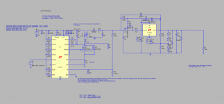
I've attached the LTSpice model - this is takes the model found in the previously referenced thread then applies:
* Updated transformer for 50A Coilcraft transformer
* Adjusted the model to follow the 42A capacitor charger model but instead of 500V it's set to 200V) it also uses two mosfets in parallel for switching.
* added a 5.1ohm + 6mF cap in the feedback loop - this is a 0.5Hz LPF
* changed the load resistance to 280 ohm to give 500mA draw
* I can remove C8..
I'm currently running a model with a second 500ohm+750uF cap to see if it reduces the noise floor further.
The linear supply was, on the whole, quieter except the 100Hz and harmonics created by non-PFC current spike which needed some further draconian LPF to get them to -90dB which meant even more power needed.
This is a non-isolated DC-DC supply, so it would be borrowing it's isolation from the SMPS - I'd probably use a Meanwell 500W 12V isolated SMPS.
This seems to have a need for about 300W possibly 600W. I'd need to make an average plot rather than the current spikes by eye approximation.
Attachments
Last edited:
Ferryster 1068YMD UC3843 controlled im working on that.
Thread here: There is little interest in Flyback from the audio folks
https://www.diyaudio.com/forums/pow...ic-12-200-450v-100ma-flyback.html#post6340032
If you need some pointers on how you get rid of the AM/FM band interference. Look up AN101F by Jim williams
Thread here: There is little interest in Flyback from the audio folks
https://www.diyaudio.com/forums/pow...ic-12-200-450v-100ma-flyback.html#post6340032
If you need some pointers on how you get rid of the AM/FM band interference. Look up AN101F by Jim williams
Ferryster 1068YMD UC3843 controlled im working on that.
Thread here: There is little interest in Flyback from the audio folks
https://www.diyaudio.com/forums/pow...ic-12-200-450v-100ma-flyback.html#post6340032
If you need some pointers on how you get rid of the AM/FM band interference. Look up AN101F by Jim williams
Thank you - that looks good and I'll read it later tonight, there's a few interesting tools out there, but this is more specific: RF Tools | LC Filter Design Tool
I've used active LPF before however they tended to be opamp based. I've put in a 60Khz 5th order butterworth, let's see what comes out and how much drop I get keeping with passive.
The interesting thing with the LT3751 (apart from the PCB ground pad) is depending on the Feedback pin, it will switch behaviours - charge, regulate or no load.
Charge - it goes for maximum charging depending on the limits programmed.
Regulate - once charged, it then switches duty cycle with a focus to reduce noise.
No-load- it goes into async/on-demand to provide power as needed.
Naturally you can program it to always sit in charge mode, but I'm hoping that it could be made to run in regulation mode.
Running another model, but let's see..
Blue - after the first filter (and where the FB loop attaches) and Green - after the second filter! An LDO would probably do well here lol!
Early into the model but I suspect given an LDO/smaller second order, that would be great:
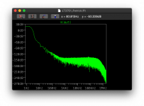
Charge - it goes for maximum charging depending on the limits programmed.
Regulate - once charged, it then switches duty cycle with a focus to reduce noise.
No-load- it goes into async/on-demand to provide power as needed.
Naturally you can program it to always sit in charge mode, but I'm hoping that it could be made to run in regulation mode.
Running another model, but let's see..

Blue - after the first filter (and where the FB loop attaches) and Green - after the second filter! An LDO would probably do well here lol!
Early into the model but I suspect given an LDO/smaller second order, that would be great:

Last edited:
Minor issue in the setup - I was following their example of setting the voltage of the RBG pin to a value - this sets the voltage at which point the charging switches off reset the charge latch.
Instead this should be tied to ground so that the pin never gets to 0.98V. Instead use FB to ensure that charge switches to regulation as needed by demand.
You can see what happened here, read is the voltage on the RBG pin.
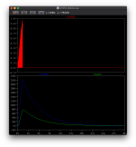
Instead this should be tied to ground so that the pin never gets to 0.98V. Instead use FB to ensure that charge switches to regulation as needed by demand.
You can see what happened here, read is the voltage on the RBG pin.

I could go with this:
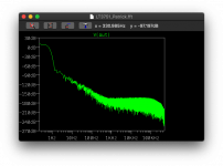
Only 8 seconds of model data, 4-8 seconds show above.
So I modelled just to understand what power would be required to drive the LPF-HPF-LPF combo:
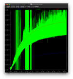
Yikes.
Green - after the diode, red - after the LPF+HPF and blue after the final LPF.. 500R causing the problem as expected.
The FB pin showing we're still in charge mode:
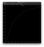
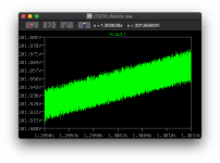
Lovely smooth output though!
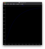

Only 8 seconds of model data, 4-8 seconds show above.
So I modelled just to understand what power would be required to drive the LPF-HPF-LPF combo:

Yikes.
Green - after the diode, red - after the LPF+HPF and blue after the final LPF.. 500R causing the problem as expected.
The FB pin showing we're still in charge mode:

Lovely smooth output though!

Last edited:
For the power, rather than attempt to max on 45A 24V which would need a hefty 1200W power supply, I've dropped the current down.
For example:
Hammond 1000VA torroidal 24Vac @ 41.7A (paralleled) + rect + smooth
Hammond 500VA torroidal 24Vac @ 20.82A (paralleled) + rect + smooth
Meanwell 400W SMPS 24Vdc @ 16.7A
Meanwell 500W SMPS 24Vdc @ 21A
Meanwell 600W SMPS 24Vdc @ 26A
The toroidal would need rectification, inrush control, no pfc, and in the end would have a lower current (this probably needing 30-32V or better at the required current).
I've set the maximum current draw lower for this next model, I've also added a snubber RC and inductance control as suggested in the application notes.
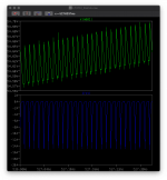
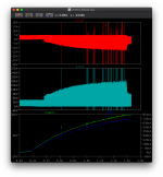
Top output from the secondary side, bottom shows the current at the 24V source - I'd set it for 24A which occurs in the transformer, but the voltage source doesn't see that given a few capacitors smoothing some of that.
~16A peaks, so average less, but 16A is about 400W. Nice.. now to let the model run for the day.. see if it will hit 200V output and the required current at the load. I'm expecting 180V so that's acceptable.
The only issue is that both the LT3751 and 3080 essentially have a soft start.. so I'm expecting a 20-30 second start time.
For example:
Hammond 1000VA torroidal 24Vac @ 41.7A (paralleled) + rect + smooth
Hammond 500VA torroidal 24Vac @ 20.82A (paralleled) + rect + smooth
Meanwell 400W SMPS 24Vdc @ 16.7A
Meanwell 500W SMPS 24Vdc @ 21A
Meanwell 600W SMPS 24Vdc @ 26A
The toroidal would need rectification, inrush control, no pfc, and in the end would have a lower current (this probably needing 30-32V or better at the required current).
I've set the maximum current draw lower for this next model, I've also added a snubber RC and inductance control as suggested in the application notes.

Top output from the secondary side, bottom shows the current at the 24V source - I'd set it for 24A which occurs in the transformer, but the voltage source doesn't see that given a few capacitors smoothing some of that.
~16A peaks, so average less, but 16A is about 400W. Nice.. now to let the model run for the day.. see if it will hit 200V output and the required current at the load. I'm expecting 180V so that's acceptable.
The only issue is that both the LT3751 and 3080 essentially have a soft start.. so I'm expecting a 20-30 second start time.
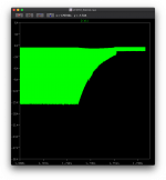
The current model is running... and has just got to regulation.
This is interesting because it throttles currently nicely during the initial startup and 6mF charging, then during regulation only seems to be switching with a maximum of 1.7A; or better put.. 24*1.7A = 40W power consumption...
There's still some more time to go until the B+ from the regulator soft start finishes at HV but this is looking good!
Last edited:
Ok, 2.4 seconds into the simulations and it's taking 64GB of disk space. I'm estimating that the 3080 soft start will take a good 6V/sec.. so it may take a while.. well 33 seconds..
Power consumption at the moment.. 924mA RMS.. so actually less than 40W.. about 22W
This may be a multi-day model.. with a .save command so I don't get a full HD.

Power consumption at the moment.. 924mA RMS.. so actually less than 40W.. about 22W
This may be a multi-day model.. with a .save command so I don't get a full HD.
Last edited:
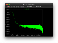
Ok at 100GB it's 2.7 seconds into the simulation.. so I think this may need a .save if this is going to run longer! I'll stop it and setup the .save - the output is looking very promising:
The mean well MSP-600 medical PSU seems to be a good starting point for this - 648W 24V 27A, PFC, isolated and some additional aux output that gives 300mA of 5V that could be used for a microcontroller. The annoying thing with the Meanwell SMPS - the SE models don't have PFC and aren't meant to be sold for mains use in the EU.
Then it's down to making the LT3751 board with twin mosfets.. not easy with a under-chip ground pin TSSP-20 so it's pretty much SMD from the start. The other pain is mounting 40A AWG14 wires onto the PCB.
Last edited:
Im an thoroughly impressed by your posts,
Can i give you some pointers, not flak?
TL783 will be far cheaper than that 3080 and requires far less components. Is stable enough, even without capacitive load. But you have to load the output either by the adjust pin current or by a 10M45S CCS into ground.
As i see it, you have put a maida style regulator behind a SMPS pre-regulator. By taking a higher voltage device you can do away with the phase shift caused by the regulator.
A simple 2N25 opto with a zener in series over the pass element(in this case a linear regulator) is enough to modulate the PWM to roughly track the voltage.
A resistor in series with the capacitor, i dont think you need it, what the simulation may not show is that this has the same effect as increasing the ESR of the capacitor behind the flyback.
- Home
- Amplifiers
- Power Supplies
- Tube use? 24->300V large cap charger with 300V 150mA reg
