Something “does not compute here”. One mV rms ripple at the rectifier capacitor, that’s -60 dBV.
That's what I get, or 2.8mVpp.

VRDN Measurements before and after changing CRC
Measurements from Post #59 with stock CRC
VRDN stock Denoiser disengaged or Cadj. only measurements:
Noise@1kHz = -135.31dBV/sqrtHz or 171.5nV/sqrtHz
PSRR@120Hz = -83.6dB
Stock denoiser engaged measurements:
Noise@1kHz =-164.93dBV/sqrtHz or 5.6nV/sqrtHz
PSRR@120Hz = -100.99dB
Add-on denoiser implemented, stock denoiser not connected to coupling cap:
Noise@1kHz = -164.54dBV/sqrtHz or 5.9nV/sqrtHz
PSRR@120Hz = -114.08dB
Add-on Dienoiser implemented, stock denoiser not connected to coupling cap:
Noise@1kHz = -176.36dBV/sqrtHz or 1.5nV/sqrtHz
PSRR@120Hz = -118.08dB
Measurements after changing CRC resistors from 0R39 to 47R
VRDN stock Denoiser disengaged or Cadj. only measurements:
Noise@1kHz = -135.28dBV/sqrtHz or 172.1nV/sqrtHz
PSRR@120Hz = -58.06dB
Stock denoiser engaged measurements:
Noise@1kHz =-164.93dBV/sqrtHz or 5.6nV/sqrtHz
PSRR@120Hz = -73.91dB
Add-on denoiser implemented, stock denoiser not connected to coupling cap:
Noise@1kHz = -165.37dBV/sqrtHz or 5.3nV/sqrtHz
PSRR@120Hz = -86.32dB
Add-on Dienoiser implemented, stock denoiser not connected to coupling cap:
Noise@1kHz = -177.29dBV/sqrtHz or 1.3nV/sqrtHz
PSRR@120Hz = -93.46dB
The PSRR numbers may look worse, but almost all levels are slightly lower which you will be able to see in the measurements of output ripple.


Very high quality LNA with an SSM2019 (less than 1nV/RtHz) from Analog. Requires a single gain setting resistor, some input caps, protection and bias resistors. Easy to work with from a few Hz to 100kHz and it's through-hole.
Thank you, I think there are some SSM2019 in my parts bin somewhere, although in SMD version if I remember correctly. If I can find them I might solder it together right now actually.
It's the one that RickRay also used. Should have between 400-570pV/sqrtHz depending on which BJTs you use. You'd need a NE5534A, a TL071 and 3x 2N4403 (or ZTX951) for the LNA circuit. You'd have to match the 3x 2N4403.
Well, call me interested. That sounds pretty good considering I should have most of those parts lying around anyway. If nobody else is interested you might as well send me a PM, I don't want to distract from the main topic of the thread too much.
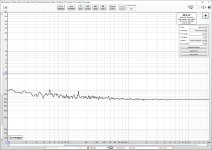
Positive Rail with stock denoiser engaged noise
View attachment 929946
Positive Rail with stock denoiser engaged output ripple
View attachment 929947
Your graphs remind me of my own tests with denoisers a while back (D-Noizator: a magic active noise canceller to retrofit & upgrade any 317-based V.Reg.). I got similar mains related spikes when I tested a denoiser on a LM317 PS that had ground planes. No spikes using the same add-on denoiser on a quick&dirty LM317 PS without ground planes.
denoiser+LM317 with ground planes
denoiser+LM317 without ground planes
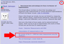
Many interesting links in the first post, thanks for the collection Mark! There seem to be quite a few popular LNA designs which makes it hard to get a good overview in a reasonable amount of time (so many long threads...). Are there any LNAs with published Gerbers apart from the one Samuel Groner designed a while back? I really can't start another design project right now so I am on the lookout for something to just put together and work. Not trying to derail the thread however, I am equally grateful for any PM with a helpful link or hint.
You might consider Scott Wurcer's LNA: My version of the G = 1000 low noise measurement amp (for Ikoflexer). I made a version with 4x 2SK170BL fets (see here). Noise is about 580pV/rtHz@1kHz but the noise profile is almost flat so the low frequency noise is very low (about 1nV/rtHz@10hz). And it runs on a single 9V battery so AC related noise is low if well shielded.
Attachments
It's a wonderful design, but there is an impedance peak @10Hz which is mentioned in the thread.
I have the little board which Patrick designed and it works quite well.
It's a wonderful design, but there is an impedance peak @10Hz which is mentioned in the thread.
Do you refer to your own post regarding the peak at 16hz?
I have measured my LNA and the frequency response is flat from 5hz to 200kHz. There is slight peaking above 200kHz depending on the source impedance.
Regulator response on transient load
One of the power supply’s most important properties, for use in the audio circuits, is their transient response. That is occasionally mentioned but almost never measured. So, we are using various power supplies in good faith that their transient response is good enough.
I’m not much into denoiser + LM regulator circuits any more, but as I have several working regulators, and have recently expanded my test bed, I took measurement on the LM317 + ordinary one BJT denoiser.
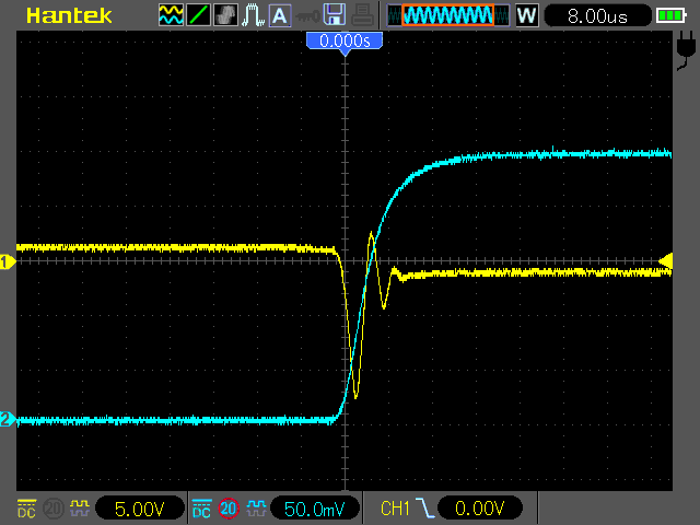
Voltage dropout on the regulator was 3.5 V, output voltage 11.5 V, load current 0.75 A @ 1 kHz with 50% duty. Blue trace is voltage on the 0.33 Ω resistor at the current sink used as load. Yellow trace is output of the regulator amplified by 1000 x. So, 5 V/div is in fact 5 mV/div.
What I learned from this measurement?
Transient response is good. Real output impedance can’t be as good as predicted by simulations. There are copper traces resistance, solder joints resistance, output connector resistance … in between.
My pcb uses power planes at all available width, and has Kelvin connection, yet measured dynamic output impedance is about 3 mΩ (voltage drop of 2 mV on load / load current). Using higher load current, I got 2 mΩ.
Long story cut short, I hope you will be happy to know that denoiser circuits have good transient response.
One of the power supply’s most important properties, for use in the audio circuits, is their transient response. That is occasionally mentioned but almost never measured. So, we are using various power supplies in good faith that their transient response is good enough.
I’m not much into denoiser + LM regulator circuits any more, but as I have several working regulators, and have recently expanded my test bed, I took measurement on the LM317 + ordinary one BJT denoiser.
Voltage dropout on the regulator was 3.5 V, output voltage 11.5 V, load current 0.75 A @ 1 kHz with 50% duty. Blue trace is voltage on the 0.33 Ω resistor at the current sink used as load. Yellow trace is output of the regulator amplified by 1000 x. So, 5 V/div is in fact 5 mV/div.
What I learned from this measurement?
Transient response is good. Real output impedance can’t be as good as predicted by simulations. There are copper traces resistance, solder joints resistance, output connector resistance … in between.
My pcb uses power planes at all available width, and has Kelvin connection, yet measured dynamic output impedance is about 3 mΩ (voltage drop of 2 mV on load / load current). Using higher load current, I got 2 mΩ.
Long story cut short, I hope you will be happy to know that denoiser circuits have good transient response.
Attachments

That is interesting. Do you think one could look at the output impedance by sensing with the LNA right at the output of the regulator to exclude track resistance, while having the supply feeding an active load? The measured signal would be the result of the output impedance.
Even if not a precise measurement, maybe this would show at least the linearity of the output impedance with frequency sweeps?
Even if not a precise measurement, maybe this would show at least the linearity of the output impedance with frequency sweeps?
- Status
- This old topic is closed. If you want to reopen this topic, contact a moderator using the "Report Post" button.
- Home
- Amplifiers
- Power Supplies
- Measurement data and techniques for Elvee's De-Noizator: all implementations