Try with 330k instead of the 1meg, see if you get shorter startup times.
Also I was just playing with the LTSpice sim and I noticed something interesting. Seems that for the positive versions of both circuits, using BC8x7 smd BJTs instead of tht BC3x7 seems to lower the noisefloor to ZTX851/ZTX951 levels.
I'll try to measure this as I'm curious. The TO-92 footprints I used should allow for SOT-23 mounting on them. Not ideal but it should work. I remember I chose that particular TO-92 footprint as it allowed for SOT-23 to also be installed on them.
I measured the noise for the positive version of the first circuit. LTSpice sim predicts 1.23nV/sqrtHz using BC327/BC337 pair for the denoiser, and it predicts 0.63nV/sqrtHz using BC817/BC807 pair.
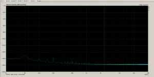
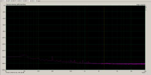
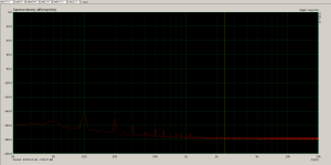
I measured the board with the BC3x7 pair and it came out at around -178.3dBV which means 1.21nV/sqrtHz. I then measured with the BC8x7 pair and it came out at -181.5dBV which means 0.84nV/sqrtHz.
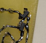
So using the BC8x7 pair results in an even lower noise floor. I made a photo of how I installed them on the BC3x7 footprints on the backside of the PCB. The top one is the BC807 and the bottom one is the BC817.
This seems to be valid for both positive versions of both circuits. For some reason the negative versions don't have a lower noisefloor with the BC8x7 pair instead of BC3x7, but they do simulate a lower noisefloor with the ZTX pair.
First photo is measurement of noisefloor with BC3x7.
Second photo is measurement of noisefloor with BC8x7.
Third photo is how I installed the BC8x7 on the BC3x7 footprints.
I measured the board with the BC3x7 pair and it came out at around -178.3dBV which means 1.21nV/sqrtHz. I then measured with the BC8x7 pair and it came out at -181.5dBV which means 0.84nV/sqrtHz.
So using the BC8x7 pair results in an even lower noise floor. I made a photo of how I installed them on the BC3x7 footprints on the backside of the PCB. The top one is the BC807 and the bottom one is the BC817.
This seems to be valid for both positive versions of both circuits. For some reason the negative versions don't have a lower noisefloor with the BC8x7 pair instead of BC3x7, but they do simulate a lower noisefloor with the ZTX pair.
First photo is measurement of noisefloor with BC3x7.
Second photo is measurement of noisefloor with BC8x7.
Third photo is how I installed the BC8x7 on the BC3x7 footprints.
Attachments
Yeah, well there's more!
So apparently, opposed to LM317+denoiser, these discrete circuits have a really low noise with just the denoiser. So basically to switch from the dienoiser circuit to the denoiser one you just have to short the 560R resistor thus taking the second dienoiser transistor out of the circuit.
Playing with the sim it seems that with either BC817 or ZTX851 you'd get the noisefloor at around 0.42 to 0.47nV/sqrtHz.
I did measure with just the denoiser and the noise is a touch lower than with the dienoiser. It measured at -182.13dBV which means 0.78nV/sqrtHz as opposed to the 0.84nV/sqrtHz of the dienoiser. But I had the pcb on the desk, with no shielding.
So if you'd like this even lower noisefloor, you could sacrifice some PSRR and output impedance performance and go with denoiser, and you could compensate for PSRR with the capacitance multiplier.
The output impedance for the first circuit changes from around 0.4mOhm with dienoiser to around 3mOhms with just the denoiser circuit, from LTSpice sim.
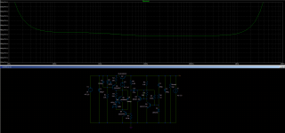
First picture is noisefloor with denoiser circuit simulated in LTSpice, second picture is the measured noisefloor with the denoiser circuit instead of the dienoiser one (and BC817).
edit: The negative versions don't benefit this much from switching to BC8x7, but the negative versions with ZTX951 do go to around 0.45nV/sqrtHz with denoiser in LTSpice sim.
So apparently, opposed to LM317+denoiser, these discrete circuits have a really low noise with just the denoiser. So basically to switch from the dienoiser circuit to the denoiser one you just have to short the 560R resistor thus taking the second dienoiser transistor out of the circuit.
Playing with the sim it seems that with either BC817 or ZTX851 you'd get the noisefloor at around 0.42 to 0.47nV/sqrtHz.
I did measure with just the denoiser and the noise is a touch lower than with the dienoiser. It measured at -182.13dBV which means 0.78nV/sqrtHz as opposed to the 0.84nV/sqrtHz of the dienoiser. But I had the pcb on the desk, with no shielding.
So if you'd like this even lower noisefloor, you could sacrifice some PSRR and output impedance performance and go with denoiser, and you could compensate for PSRR with the capacitance multiplier.
The output impedance for the first circuit changes from around 0.4mOhm with dienoiser to around 3mOhms with just the denoiser circuit, from LTSpice sim.
First picture is noisefloor with denoiser circuit simulated in LTSpice, second picture is the measured noisefloor with the denoiser circuit instead of the dienoiser one (and BC817).
edit: The negative versions don't benefit this much from switching to BC8x7, but the negative versions with ZTX951 do go to around 0.45nV/sqrtHz with denoiser in LTSpice sim.
Attachments
Last edited:
A few members asked me to start a new thread for these two circuits. I made them while playing with the denoiser circuit presented in this thread. The denoising circuit was developed by Elvee and improved by Diego.
I applied the denoising circuit to two types of discrete regulators and it improved their performance by quite a bit. They both have a PSRR of more than -140dB depending of output voltage/current.
I also made some pcb designs for both, with and without a capacitance multiplier. Depending on your needs it can improve the PSRR to around -200dB.
Both circuits can be made with regular parts but for maximum performance certain BJTs should be used. Voltage reference can be either two LEDs in series, Zener or even LM329. PCBs have footprints for all of these. Out of all three options LEDs have the worst tempco but it's usable.
Voltage output range should be pretty wide and limited by capacitor voltage rating and transistors used. In simulation I managed to get 30V/4A output from both circuits but some modifications are required for mora than 1A current output.
For up to 30Vout you could use two LEDs in series but above this you should switch to Zeners. I tested with IR, red, yellow, orange and green LEDs and worked fine with either. I tested this for the Vref LEDs and also the CCS LED. I recommend using red LEDs, you can use the model in the LTSpice sim files so you can test your needed part values.
I built and measured both designs with earlier versions of the posted pcbs.
If you have questions about recommended part values for certain voltage/current output I will try to help.
I'll attach the pcb designs in the next post.
I need help for output voltage 5 volt at 3 Amp, for my raspberry pi and DAC.
Thank you for your help and support
Yes R14 from your schematic. Try 330k instead of 1meg.
You could use BC8x7 instead of the ZTX ones. I'll measure them and post the results. But I think the ZTX ones also offer some extra PSRR performance. They are expensive though.
I've replaced 1Meg with 220K (in LTSpice there is no difference between 330K and 220K so I went with 220K) and it powers up faster, about 5sec.
I've added bypass caps you suggested. Works like a charm for now.
Now I'll try version with positive feedback.
Can you also test circuit one without CM and with example 12V /250mA output?
Thx again for everything i think i will built discrete one circuit.
I'll try and measure it these days and come back with results and best part values.
I've replaced 1Meg with 220K (in LTSpice there is no difference between 330K and 220K so I went with 220K) and it powers up faster, about 5sec.
I've added bypass caps you suggested. Works like a charm for now.
Now I'll try version with positive feedback.
Yeah I just measured the noise of different BJTs in the circuit and mine powers up between 3-5 seconds or so each time.
Seems like a good alternative to BC337/BC327 is the 2N4401/2N4403 pair. Almost as good as the BC817/BC807 one.
For denoiser only:
BC337: 1.17nV/sqrtHz (around 3-4kHz).
BC817: 0.7nV/sqrtHz
2N4401: 0.76nV/sqrtHz
MPSA06: 0.7nV/sqrtHz
For dienoiser:
BC3x7: 1.2nV/sqrtHz
BC8x7: 0.8nV/sqrtHz
2N440x: 0.84nV/sqrtHz
MPSAx6 : 0.78nV/sqrtHz
I suggest you use the MPSA06/MPSA56 combo for denoiser BJTs. They seem to increase the PSRR, at least for the first circuit, closer to the predicted 156dB from LTSpice. For the positive feedback version I measured 152.6dB PSRR with MPSAx6. BC8x7 measured 146dB.
Denoiser PSRR was around 125dB for both.
Noise density measurement showed the same noise for both types, around 956pV/√Hz for the dienoiser and around 840pV/√Hz for the denoiser version. So all previously posted noise values should be in reality around 150pV/√Hz higher.
I'm still trying to get my measuring setup closer to reality.
This PSRR increase from MPSAx6 seems to be valid just for these discrete versions. For LM317N + de/dienoiser the BC8x7 pair seems to give better results as noise and PSRR but just by little.
edit: these noise values should contain my LNA noise as well, which should be around 0.55nV/√Hz. I'm not sure how to calculate just the supply noise atm. Will look into it.
Last edited:
I'm using a 60dB LNA but for ADC I'm using my PC's onboard soundcard which is not so great. But a Focusrite should work way better. They have a decent ADC/input stage.
Member tombo56 provided the math for how to extract just the supply noise density values here:
Measurement data and techniques for Elvee's De-Noizator: all implementations
So the dienoiser noise would come out at around 840pV/√Hz and the denoiser at around 637pV/√Hz after we extract the LNA's noise from the measured values.
Of-course these should still be taken with a grain of salt. I only looked at the 10kHz-20kHz spectrum for these measurements as that's where my ADC is cleaner.
I may upgrade to a better ADC at some point and retake these measurements.
Current best designs
Hi, are the most accurate board designs collected in post #11 or did I miss other updates? I want to order some to test and want to get the corrected\tested versions.
I will probably have spares after the order so I will post back to see if anyone needs one.
Owen
Hi, are the most accurate board designs collected in post #11 or did I miss other updates? I want to order some to test and want to get the corrected\tested versions.
I will probably have spares after the order so I will post back to see if anyone needs one.
Owen
- Home
- Amplifiers
- Power Supplies
- Discrete regulators with denoiser