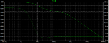
What's the best Q factor for RLC PSU? I read 1/2 = 0.5 = Q critical damped or have I to look for low quality factor (Q < 1⁄2) is said to be overdamped or high quality factor (Q > 1⁄2) is said to be underdamped?
If I understood correctly first I have to look for a resonant frequency out of our range of hearing?
TIA
If I understood correctly first I have to look for a resonant frequency out of our range of hearing?
TIA
Last edited:
In my opinion it's purely a matter of opinion (!). Different engineers have different preferences and all we can say with definitive certainty is "xxx is the best FOR ME".
Some engineers prefer to optimize in the time domain, and for them, the Bessel choice of Q is preferred.
Other engineers prefer to optimize in the frequency domain, and for them, the Butterworth choice of Q is preferred.
I, myself, prefer to design for the worst case situation in which all components are at the outer edges of their tolerance bands. If the inductor's tolerance is ±15% then I do the calculations with 0.85*Lrated and again with 1.15*Lrated.
If the capacitor's tolerance is ±20% then I do the calculations with 0.80*Crated and again with 1.20*Crated.
If the resistor's tolerance is ±5% then I do the calculations with 0.95*Rrated and again with 1.05*Rrated.
If there are "N" components, I do the calculations (2 raised to the power N) times. So if there are 3 components (R, L, C), I do the calculations (2^3) = 8 times. (2 different inductances) * (2 different capacitances) * (2 different resistances).
I'm not going to say this is BEST approach; rather, it's merely what makes me feel comfortable. Other engineers have other criteria.
I, myself, prefer to design for the worst case situation in which all components are at the outer edges of their tolerance bands. If the inductor's tolerance is ±15% then I do the calculations with 0.85*Lrated and again with 1.15*Lrated.
I did buy the book you recommended a few years ago! "Tolerance Design of Electronic Circuits". Small world.
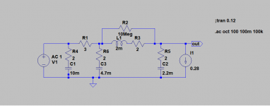
PSUD2 will simulate the differential mode inductance of your choke, which is a key aspect of mains frequency ripple estimation. The ripple and low frequency resonance simulation is only as good as your awareness of part values that influence those issues.
If you aren't confident in the PSUD2 results, because you can't see any oscillation to a step load change, then I'd suggest posting a clip of your simulation front page, and summarise how you determined part values, as posters may be able to see a concern.
Using a CM choke in that location has a few subtle issues, including how rectification noise may bypass the CM choke via any capacitance path from secondary winding to chassis.
Last edited:
I don't know how to simulate CMC, please help.
Common mode choke simulation with LTSpice - Q&A - Design Tools and Calculators - EngineerZone
What is your transformer? Or did you make the measurements that allowed the secondary winding voltage and effective resistance to be included in the sim?
Are your diodes 1N4007?
What are your cap types (datasheet)?
Does your load have a voltage range, and a current range, for normal operation? Ie. have you constructed the 'load' and made any measurements. If that is not known, then do you have circuitry?
Are your diodes 1N4007?
What are your cap types (datasheet)?
Does your load have a voltage range, and a current range, for normal operation? Ie. have you constructed the 'load' and made any measurements. If that is not known, then do you have circuitry?
Last edited:
- Status
- This old topic is closed. If you want to reopen this topic, contact a moderator using the "Report Post" button.
- Home
- Amplifiers
- Power Supplies
- Q factor RLC PSU