Dear friends, I need some help. What is the easiest way to reduce ±60V to ±15V with sufficient performance?
I initially plan to use LM317 tracking preregulator circuit and add TVS diodes for clamping protection. Doing so can meet the requirements while getting the powerful performance of LM317 and is relatively simple, but there are some problems that have not been resolved:
1. At the moment of starting, due to the need to charge the load capacitor, the load will be exposed to a dangerous environment far exceeding ±15V.and the LM317 is easily damaged. If I use 30V TVS diodes on each LM317 and connect 17V TVS diodes in parallel to the output port, can I effectively protect the load from overvoltage damage?
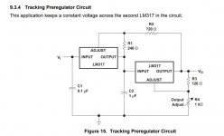
2. At present I know that LM317 can make a tracking preregulator circuit to achieve a voltage drop of 50-60V. So, can LM337 corresponding to LM317 make negative voltage tracking preregulator circuit?
3. I considered using LM783, but it does not have a negative voltage LDO.Are there other more concise high-performance positive and negative voltage regulator circuits?
thank you all!:D
I initially plan to use LM317 tracking preregulator circuit and add TVS diodes for clamping protection. Doing so can meet the requirements while getting the powerful performance of LM317 and is relatively simple, but there are some problems that have not been resolved:
1. At the moment of starting, due to the need to charge the load capacitor, the load will be exposed to a dangerous environment far exceeding ±15V.and the LM317 is easily damaged. If I use 30V TVS diodes on each LM317 and connect 17V TVS diodes in parallel to the output port, can I effectively protect the load from overvoltage damage?
2. At present I know that LM317 can make a tracking preregulator circuit to achieve a voltage drop of 50-60V. So, can LM337 corresponding to LM317 make negative voltage tracking preregulator circuit?
3. I considered using LM783, but it does not have a negative voltage LDO.Are there other more concise high-performance positive and negative voltage regulator circuits?
thank you all!:D
Attachments
Last edited:
First bring down by switching converter to +/- 20v, than apply linear regulator.
Positive and negative voltage; 400mA current; low-noise switching converter.
Is there a specific model recommendation?
Is the high frequency noise as low as that of a linear regulator?
Thank you !

Positive and negative voltage; 400mA current; low-noise switching converter.
45*0.4= 18W per rail of wasted energy if you go for a linear solution, so yes a switching solution is the way to go.
The easy but not cheap way is to use two isolated dc-dc converter such as the SPB09C-15 from Meanwell. 36 to 75v input, 15v@600ma output. But about 15$ each... Follow that by a CLC filter.
WHAT-IS-THE-LOAD-CURRENT?Dear friends, I need some help. What is the easiest way to reduce ±60V to ±15V with sufficient performance?
Are you asking for a solution or confirmation on your already decided plan?I initially plan to use LM317 tracking preregulator circuit and add TVS diodes for clamping protection.
We lack important data.
And not sure about your "clamping" either.
????????Doing so can meet the requirements while getting the powerful performance of LM317 and is relatively simple, but there are some problems that have not been resolved:
No.1. At the moment of starting, due to the need to charge the load capacitor, the load will be exposed to a dangerous environment far exceeding ±15V.
If anything, load will be *under* volted until any capacitor across it charges.
and the LM317 is easily damaged. If I use 30V TVS diodes on each LM317 and connect 17V TVS diodes in parallel to the output port,

Which overvoltage?can I effectively protect the load from overvoltage damage?
2. At present I know that LM317 can make a tracking preregulator circuit to achieve a voltage drop of 50-60V. So, can LM337 corresponding to LM317 make negative voltage tracking preregulator circuit?
3. I considered using LM783, but it does not have a negative voltage LDO.Are there other more concise high-performance positive and negative voltage regulator circuits?
You are running too fast for us to catch up
, please supply full details on your load requirements first.And welcome to the Forum
Google Translate seems to be unable to fully express my thoughts, haha. I plan to get a voltage of ±60V from the main power supply of the power amplifier because I don't want to add new windings to the transformer. While maintaining good performance, it needs to be reduced to ±15V in the simplest way. At least 200ma current is used to drive 5-6 operational amplifiers. It has a huge heat sink, so it can get good heat dissipation support, and I don't care about power consumption. Based on this requirement, I first thought of lm317/lm337 because it can provide good enough performance and is simple enough, but its maximum withstand voltage cannot meet the requirements. I thought of using two lm317s in series to solve the power consumption and withstand voltage problems, and considered using TVS to protect the lm317 from accidental damage. I don't know whether the whole circuit is strong enough after using TVS, or whether the operational amplifier will be damaged by accidental ultra-high voltage. If this idea is feasible, can lm337 do the same? This is my initial thought.
WHAT-IS-THE-LOAD-CURRENT?
Are you asking for a solution or confirmation on your already decided plan?
We lack important data.
And not sure about your "clamping" either.
????????
No.
If anything, load will be *under* volted until any capacitor across it charges.
Which overvoltage?
You are running too fast for us to catch up
And welcome to the Forum
I made a mistake. When the capacitor starts to charge, LM317 will bear all the voltage, TVS will protect it. The load will not withstand excessive voltage. Thank you!
You need a preregulator to lower the regulator input voltage, it is above the specs.
How much current is required at 15V?
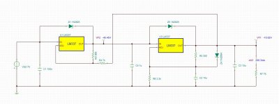
View attachment 899095
This is good to 200mA, it gives 23V out
Using a pre-conditioner is indeed a good way.it is simple enough. Use high withstand voltage BJT to withstand huge voltage difference.
thank you!
I had this trouble of a too high voltage for a LM317.
My solution was using a TL431 ( a shunt regulator ) and a BJT to deal with the high voltage.
In this solution, the BJT emitter is at the regulated output, the collector at the unregulated voltage. The TL431 has the anode at ground, the cathode at the BJT base, its ref input senses the regulated output voltage with an appropriate voltage divider.
For an improved low ripple, I use a CCS to feed de BJT base and give at least 1mA to the TL431.
This solution is my favorite and is fine for up to 35V positive regulated PSUs.
Very flexible using Skyzlar pair for high current.
Can one dream simpler ?
1 Pass BJT.
1 Shunt regulator: TL431.
1 Output cap ( about 100uF )
1 Resistor divider: 2 resistors.
1 CCS: 2 cheap BJT + 2 Resistors.
For +15V -15 V. Make two positive regulators, feed them from two independent secondary windings with 2 diode bridges. Connect outputs so to have your central ground.
This is far better than the usual center tap winding, followed by pos and neg complementary stuff that only advantage is purely cosmetic.
This might not be possible if you are getting your +/-60v from an existing supply...
edit: btw, if this is for opamps, with decent psrr to start with, one might not need a lm317/337 pair at all. A pair of big bjt (one pnp, one npn), two 15v zeners, two resistors and two output caps are all that's needed if ample dissipation is available. Not efficient though.
edit: btw, if this is for opamps, with decent psrr to start with, one might not need a lm317/337 pair at all. A pair of big bjt (one pnp, one npn), two 15v zeners, two resistors and two output caps are all that's needed if ample dissipation is available. Not efficient though.
Last edited:

00940 is quite on the spot.
No need for a tour de force using inadequate LM317 and praying they share voltage equally which will NOT fail safe under any problems, use parts which can each stand 60V rails (and more, play it safe), period.
Solution is robust and cheap:
1) use TIP31C-32C with 2k2 2W resistors Collector to Base and 20-22V 1W Zeners Base to Ground as preregulators.
You´ll get 19-21V DC
You may add small 10uF electrolytics from emitter to ground
2) use LM7815-7915 as final regulators, following datasheet suggestions.
That´s it.
Forget the dangerous idea of clamping diodes as you mentioned, they will either "do nothing" or explode.
Simulate it if you wish, not really necessary, I have been doing this thousands of times for decades, in abused Guitar amps and powered mixers.
No need for quirky switchdown preregulators or anything else, everything off the shelf stuff.
- Status
- This old topic is closed. If you want to reopen this topic, contact a moderator using the "Report Post" button.
- Home
- Amplifiers
- Power Supplies
- What is the simplest and most efficient way to reduce ±60V to ±15V?