This project has NOT been practically made and may not be soon, because of difficulties to home make this project and lack of equipment, such as an oscilloscope, etcetera.
This is, also, why I want to see the comments and the opinions of others.
A possible idea is to make an integrated system with a power supply, an amplifier, two speakers, etcetera, which, does not have any mechanical inputs and outputs, such as jacks, sockets, speaker connectors, potentiometers, etcetera, instead, everything is integrated and controlled by a remote control or through Bluetooth.
The same applies to the input signals, which are not mechanically connected to the system with jacks and sockets, but, instead, through Bluetooth only.
Because the system does not have any mechanical inputs, outputs and control, the case can be grounded to Ground and Neutral can be used as an internal, system ground. Thus, Ground will NOT be connected to Neutral, which means, such a system is as safe as a stove or power tools, even, safer.
The document was supposed to be very tiny, but, became still tiny, yet, not as tiny as intended. The schematics are in the addendum, so, please, scroll all the way with Ctrl Home.
Thanks for your help and advise!
Here is the document :
Transistor Based, Switched Capacitor Power Supply - Google Drive
Hi Steven,
Bear in mind diyAudio topics according to the rules must be safe. I would think that excludes direct-off-the-mains supplies with amplifiers and speaker outputs which float with mains voltages to ground (relative to metal chassis etc).
This would apply to full-wave bridge rectified mains where the capacitor terminals has alternate mains voltage to ground.
It may not apply to the half-wave rectifier or the voltage doubler - effectively two half-wave rectifiers (as you discuss in your document) where one side of the capacitor IS connected to the mains neutral which is also 'bonded' to earth in most countries.
I say "may not apply" because I am not an authority on the legality of direct-off-the-mains half-wave rectifier or doubler arrangements even in my country. It may depend on whether it is for DIY and a never for sale item and a never for export. It depends on each countries regulations and standards.
Anyone, please correct me if I am wrong or missed something important or if I confused some .
.
In the 1960's through 1970's most tube based TV's in New Zealand and Australia had direct-off-the-mains supplies and you could not touch their chassis.and anything to earth at the same time. The UHF tuner had a ferrite core to isolate the mains from the TV aerial - but sometimes the insulation failed and sent mains down to another TV sharing the same aerial giving a shock to anyone touching the other TV's aerial connector (as was my experience). Also IIRC Bob Carver's first "cube amp" before he sold any was a transformerless direct-off-the-mains amp.
BTW I suggest as a precaution you should add a note at the beginning to the effect that the ideas involve direct-off-the-mains power and anyone attempting to make these should take extra precautions with earthing as well as the higher voltages can be lethal. Using an isolation transformer during development would be a wise idea. Also an earth leakage relay in the mains would be a good idea.as well. Once developed and in a suitable enclosure (with any metal that can be touched grounded) then an isolation transformer is not needed (it may depend on each countries regs), but the earth leakage relay would still be a good idea.
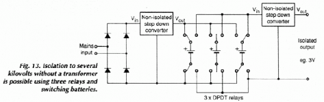
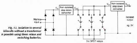
BTW An article on direct-off-the-mains supplies was published in Electronics World Sept 1997 and can be seen on MyDrive/My Articles "Switched-capacitor-power-supplies" and the patent referred to is also on MyDrive. One idea for isolation without a transformer to 3V for PC's was to use relays and flying batteries (below) but I have never seen this used commercially. For audio amps you don't need the second down converter on the isolated side.

Bear in mind diyAudio topics according to the rules must be safe. I would think that excludes direct-off-the-mains supplies with amplifiers and speaker outputs which float with mains voltages to ground (relative to metal chassis etc).
This would apply to full-wave bridge rectified mains where the capacitor terminals has alternate mains voltage to ground.
It may not apply to the half-wave rectifier or the voltage doubler - effectively two half-wave rectifiers (as you discuss in your document) where one side of the capacitor IS connected to the mains neutral which is also 'bonded' to earth in most countries.
I say "may not apply" because I am not an authority on the legality of direct-off-the-mains half-wave rectifier or doubler arrangements even in my country. It may depend on whether it is for DIY and a never for sale item and a never for export. It depends on each countries regulations and standards.
Anyone, please correct me if I am wrong or missed something important or if I confused some
.In the 1960's through 1970's most tube based TV's in New Zealand and Australia had direct-off-the-mains supplies and you could not touch their chassis.and anything to earth at the same time. The UHF tuner had a ferrite core to isolate the mains from the TV aerial - but sometimes the insulation failed and sent mains down to another TV sharing the same aerial giving a shock to anyone touching the other TV's aerial connector (as was my experience). Also IIRC Bob Carver's first "cube amp" before he sold any was a transformerless direct-off-the-mains amp.
BTW I suggest as a precaution you should add a note at the beginning to the effect that the ideas involve direct-off-the-mains power and anyone attempting to make these should take extra precautions with earthing as well as the higher voltages can be lethal. Using an isolation transformer during development would be a wise idea. Also an earth leakage relay in the mains would be a good idea.as well. Once developed and in a suitable enclosure (with any metal that can be touched grounded) then an isolation transformer is not needed (it may depend on each countries regs), but the earth leakage relay would still be a good idea.
I'm not sure exactly what circuit you have in mind here. Could you add a basic circuit to clarify please.One of the ways to make a transformerless power supply from the standard, mains, hot and neutral voltage is to convert this AC voltage to a DC with a bridge, scale down the DC and use a standard, switched flying capacitor, charge pump inverter, such as LTC7820 and the magnificent TDK Lambda converters
BTW An article on direct-off-the-mains supplies was published in Electronics World Sept 1997 and can be seen on MyDrive/My Articles "Switched-capacitor-power-supplies" and the patent referred to is also on MyDrive. One idea for isolation without a transformer to 3V
for PC's was to use relays and flying batteries (below) but I have never seen this used commercially. For audio amps you don't need the second down converter on the isolated side.Attachments
Last edited:
If one of the relay contacts gets stuck and the other switches over someone can get killed.
Even if safety relays are used which prevent this by locking the contact pairs together, the contact clearance is below legal requirements.
Big contactors may provide the clearance, but they are LOUD.
Even if safety relays are used which prevent this by locking the contact pairs together, the contact clearance is below legal requirements.
Big contactors may provide the clearance, but they are LOUD.
No, this is not a commercial power supply and is not to be made for to be sold.
Yes, the best way would be to use a transformer. However, the transformer must not be very powerful and not of high voltage, or, the device would be even more unsafe than the straight off the mains ones. I have found a switching transformer, which, may be suitable for audio : FA2443-AL.
I think the most important safety requirement is to have the chassis grounded and not connected to neutral. Thus, whatever happens inside, the case will always be connected to ground and whether a faulty hot or neutral touches the case is irrelevant as they would go to ground ( and the fuses would blow in case hot touches case ). This, however, does not allow to connect equipment, because, the outputs and inputs provide case connections, connected to their input and output connections and this would connect neutral to ground. This is why I have mentioned such a power supply be used only without inputs and outputs and without any potentiometers and any galvanic control. Just an infrared or radio ( Bluetooth ) controls and a radio ( Bluetooth ) inputs. No speaker out[puts too. Speakers must be integrated. Even better, the enclosure must be fiberglass or plastic.
Stoves, Air Conditioning, etcetera, take 240V and do not have transformers. Even in case anyone is to put a transformer in a stove, this transformer would be very powerful and high voltage and would not provide any protection despite the isolation. Thus, the transformers used must be low voltage and, even better, low power.
Most standards specify only a single fault protection. This means any metallic case must be grounded, so, in case of a fault when hot touches case, hot goes to ground and nothing happens. However, in case of this and a faulty ground connection, the case may be disconnected from ground. However, this is a double fault scenario. 1. Hot touches case and 2. Ground connection to case is broken. Because this is a double fault and not a single fault, such scenario is considered safe.
Yes, another condition is any inputs and outputs not to be connected to mains in any way. I would add, they must not be, indirectly or directly, connected to a high voltage and power transformer. Thus, any tube amplifiers with high voltage and high power transformers and high voltage converters may also be unsafe.
As far as I remember, LTC7820 is a voltage converters, which, with one of the arrangements ( the schematics is in the datasheet ), LTC7820 can be configured to be a 10A, 24V, voltage inverter and make a good negative voltage from a positive one.
The " magnificent TDK Lambda converters " are AC to DC or DC to DC integrated converters. I am not sure whether they have a switching transformer inside. An example for AC to DC integrated converter is KMS40-15. There are other AC to DC converters in the KM brand. They ca be connected directly to mains. An example of a DC to DC integrated converter may be PH150A280-15. There are other DC to DC converters in the PH-A280 brand.
All TDK Lambda converters are expensive.
Hi Holmer,If one of the relay contacts gets stuck and the other switches over someone can get killed.
Even if safety relays are used which prevent this by locking the contact pairs together, the contact clearance is below legal requirements.
Big contactors may provide the clearance, but they are LOUD.
Isn't sticking of relays due to welding? But in my arrangement welding is prevented by using 3 relays, so when one is 'flying' it doesn't break voltage, so in principle no arcing or welding.
Clearance is then determined by air breakdown, which I think must be several kV for relays like the relays we use for speaker protection.
Since this is a non-standard application existing standards are probably not relevant. But as a lone designer wouldn't want to get special approvals at today's rates.
It was just a crazy idea that I thought could be used for audio amps to reduce weight. Don't all new ideas appear crazy at first?
Another clarification for the general document, I would like to add, is, the document shows there is a transformer, but, this transformer is provided either by the power distribution industry or by the building construction company. This is a high power transformer. Thus, an additional, low power transformer is necessary for most any design.
However, the circuit and the circuit idea can be used after an additional transformer, although, perhaps, there are much better circuit solutions for such a case.
The circuit can be used for high voltage transformers for multi voltage applications, but, again, although higher voltage transformers are considered safe, they are not.
Any voltage higher than 60V is considered unsafe. This is why people can lick 9V batteries and can touch the standard, 12V, high power, low voltage car battery, people should not do this with higher than 60V batteries and supplies.
Thus, the maximum, safe, dual power supply, whether from batteries or transformers is lower than +- 30VDC, because, to make +- 30VDC one needs a converter, which, usually needs some overhead voltage.
Thus, a power supply of +- 25V can be considered the highest safe power supply. This leaves 5V overhead, which is OK with most 78xx and 79xx converters with bipolar buffers.
However, when the converter is buffered by a MOSFET, the overhead voltage is Ugs, which, typically, is 10V and, therefore, the highest safe voltage is +- 20V.
In other words, the rule is, the highest voltage difference at and after the secondary of a transformer must be lower than 60V.
60VDC is considered maximum. Better to be lower than this.
Then, on the top of this, there may be people with different sensitivity, different body and skin impedances, etcetera. Also, these 60V have been defined for the general case and, the voltage may need to be even lower when there is a possibility for the user to touch with two hands, in which case the path of the current goes through the heart.
There was a joke amongst digital and computer engineers : " Any voltage, higher than 5V, do not touch! "
I would say, any dual voltage higher than +- 18V, do not touch!
Ah, Steven, now I can see what you are trying to do. The "Vc" and "Ve" in Figs 0-2 connects to the series transistors in Fig.3 to drop the rectified mains voltage of up to +/-180V down to +/-18V for supplying amplifiers.
Even if you switch the series transistors fast you will always end up with the same power losses as a linear series-pass .regulator. This is a fact of life when charging a capacitor without using any inductor (like switching power supplies use). This issue was a question covered in my engineering course and it is covered in some physics texts.
In your circuit you drop 180-18V or about 160V so the efficiency (Pout/Pin) is only 11%. Again it is the same if you pulse the power through as when you use a series pass regulator.
BTW the EW 1997 article I mentioned covers variable ratio charge pumps with minimal power losses. The link is EW-WW_Hegglun_SCPS-Switched-capacitor-power-supplies_Sep-1997.pdf - Google Drive
Another way to make charge pumps variable ratio using PWM is to incorporate a small inductor in the diode path as shown in this patent Hegglun_SCPS-AU729687-patent-sealed_1998.pdf - Google Drive
Thanks for mentioning the LTC7820. I think I missed that one. It is similar to the one in the EW 97 article. I'm pleased someone finally made an IC for this job -- albeit only for a fixed ratio. Nice work ADI.. The patent can be seen here US9484799B2 - Switched capacitor DC-DC converter with reduced in-rush current and fault protection
- Google Patents by Jindong Zhang and Jian Li.
Even if you switch the series transistors fast you will always end up with the same power losses as a linear series-pass .regulator. This is a fact of life when charging a capacitor without using any inductor (like switching power supplies use). This issue was a question covered in my engineering course and it is covered in some physics texts.
In your circuit you drop 180-18V or about 160V so the efficiency (Pout/Pin) is only 11%. Again it is the same if you pulse the power through as when you use a series pass regulator.
BTW the EW 1997 article I mentioned covers variable ratio charge pumps with minimal power losses. The link is EW-WW_Hegglun_SCPS-Switched-capacitor-power-supplies_Sep-1997.pdf - Google Drive
Another way to make charge pumps variable ratio using PWM is to incorporate a small inductor in the diode path as shown in this patent Hegglun_SCPS-AU729687-patent-sealed_1998.pdf - Google Drive
Thanks for mentioning the LTC7820. I think I missed that one. It is similar to the one in the EW 97 article. I'm pleased someone finally made an IC for this job -- albeit only for a fixed ratio. Nice work ADI
.. The patent can be seen here US9484799B2 - Switched capacitor DC-DC converter with reduced in-rush current and fault protection - Google Patents by Jindong Zhang and Jian Li.
Last edited:
Another clarification for the general document, I would like to add, is, the document shows there is a transformer, but, this transformer is provided either by the power distribution industry or by the building construction company. This is a high power transformer. Thus, an additional, low power transformer is necessary for most any design.
However, the circuit and the circuit idea can be used after an additional transformer, although, perhaps, there are much better circuit solutions for such a case.
The circuit can be used for high voltage transformers for multi voltage applications, but, again, although higher voltage transformers are considered safe, they are not.
Any voltage higher than 60V is considered unsafe. This is why people can lick 9V batteries and can touch the standard, 12V, high power, low voltage car battery, people should not do this with higher than 60V batteries and supplies.
Thus, the maximum, safe, dual power supply, whether from batteries or transformers is lower than +- 30VDC, because, to make +- 30VDC one needs a converter, which, usually needs some overhead voltage.
Thus, a power supply of +- 25V can be considered the highest safe power supply. This leaves 5V overhead, which is OK with most 78xx and 79xx converters with bipolar buffers.
However, when the converter is buffered by a MOSFET, the overhead voltage is Ugs, which, typically, is 10V and, therefore, the highest safe voltage is +- 20V.
In other words, the rule is, the highest voltage difference at and after the secondary of a transformer must be lower than 60V.
60VDC is considered maximum. Better to be lower than this.
Then, on the top of this, there may be people with different sensitivity, different body and skin impedances, etcetera. Also, these 60V have been defined for the general case and, the voltage may need to be even lower when there is a possibility for the user to touch with two hands, in which case the path of the current goes through the heart.
There was a joke amongst digital and computer engineers : " Any voltage, higher than 5V, do not touch! "
I would say, any dual voltage higher than +- 18V, do not touch!
These comments stem from someone without the requisite engineering qualifications and knowledge of regulatory electrical safety standards.
The concept and circuit is lethal.
This thread should be deleted post-haste.
Ah, Steven, now I can see what you are trying to do. The "Vc" and "Ve" in Figs 0-2 connects to the series transistors in Fig.3 to drop the rectified mains voltage of up to +/-180V down to +/-18V for supplying amplifiers.
Even if you switch the series transistors fast you will always end up with the same power losses as a linear series-pass .regulator. This is a fact of life when charging a capacitor without using any inductor (like switching power supplies use). This issue was a question covered in my engineering course and it is covered in some physics texts.
In your circuit you drop 180-18V or about 160V so the efficiency (Pout/Pin) is only 11%. Again it is the same if you pulse the power through as when you use a series pass regulator.
BTW the EW 1997 article I mentioned covers variable ratio charge pumps with minimal power losses. The link is EW-WW_Hegglun_SCPS-Switched-capacitor-power-supplies_Sep-1997.pdf - Google Drive
Another way to make charge pumps variable ratio using PWM is to incorporate a small inductor in the diode path as shown in this patent Hegglun_SCPS-AU729687-patent-sealed_1998.pdf - Google Drive
Thanks for mentioning the LTC7820. I think I missed that one. It is similar to the one in the EW 97 article. I'm pleased someone finally made an IC for this job -- albeit only for a fixed ratio. Nice work ADI
- Google Patents by Jindong Zhang and Jian Li.
Thank you for your post! Excellent as usually!
What I try to do is, yes, I would like to convert 170VDC nominal to < 18VDC. Yes, this is for amplifiers. Most of them are rated for +- 15VDC and can withstand maximum supply voltage of +- 18VDC. This is the maximum, so, a good idea is to be under +- 18VDC, although, I presume, the maximum of +- 18V is measured with 5% accuracy. Yet, better is to always be under the maximum.
To do this, yes, I switch a transistor. The output is regulated this way : I always try to switch a transistor with, say 40KHz. Whether the transistor conducts current to the output capacitor depends on two things : 1. Whether the multivibrator base emitter voltage is correct. 2. Whether the output capacitors contain voltage, which is below the zener voltage ( say, 18V ) minus Ube ( and Uf of some protection diodes ). Only when these two conditions are met will the transistor conduct current to charge the output capacitors.
Thus, the output is controlled under 18V. Of course the regulation is not perfect, because, Ube and Uf depend on the current through.
In case the output voltage is under around 18V, then, the multivibrator will open the transistor. The transistor will provide high current through the output capacitor and the load. The transistor will continue to conduct until the output capacitors are full ( around 18V ) or until the multivibrator closes the transistor, whichever comes first.
Therefore, in case of an ideal system, the transistor will either be fully open or fully closed and, in case of ideal components, the transistor will consume zero power. Again, this is an ideal case and not a real one.
A better explanation is this : the transistor is a common collector buffer, but, this buffer is switched on and off by a multivibrator, i. e., the buffer works for, say, 12us and does not work for another 12us.
And here is something I have not explained very well : when the buffer works ( 12us maximum ) and after the output capacitors are charged, the transistor, even for a few us, works as a standard buffer with Uce ~ 152V and Ice as per the load, say, 6A. This means, for these few us, the transistor is not fully open and, even theoretically and in an ideal system, the transistor will dissipate power, which is not zero, but is around 152 * 12 ~ 1800W. This, however is for a few us, <= 12us. In the worst case, this is for 12us and, then, the transistor is off for 12us, 50% duty cycle. Thus, in this worst case, the transistor consumes half of the current at half of the voltage, therefore, 1800 / 4 = 250W.
However, this is some very worst case scenario. In case the load would consume 6A, then, the transistor will have to charge the capacitor and provide 6A to the load, 12A in all, but, in such a case, the transistor would have to be fully open for all of the 12us half period and, again, theoretically, the transistor will consume zero power for all of the whole period.
I will try to explain this better in the document.
I have made a bad explanation again. I will try again.
See the attached.
Assume ideal transistors, ideal zener, ideal capacitor, ideal multivibrator.
Assume the load consumes 6A constantly.
Assume the multivibrator frequency is 40KHz, therefore the period is 25us and the half period is 12.5us.
Assume the capacitors are fully charged initially.
1. Assume the multivibrator has just switched to high. Therefore, the ideal transistor T11 is fully closed and, therefore, does not consume power. The load consumes 6A off the capacitor and, therefore, discharges the capacitor.
2. The multivibrator switches from high to 0V. The transistor, T11, is fully open immediately. The capacitor has been discharged with 6A for 12.5us, and, therefore, the voltage is lower than the zener voltage. Therefore, the fully open, ideal, T11 provides infinite current through the capacitor and 6A through the load and has a Uce of 168V maximum. Because the current is infinite, the capacitors will charge immediately to the zener voltage and close T11. When this happens, Uce of T11 = 150V.
However, the load continues to consume 6A. T11 is now a buffer which provides these 6A to the load. ( The load discharges the capacitor by an infinitely low amount of voltage. Because T11 is idea, this infinitely low voltage opens T11 and the same cycle repeats in a typical feedback way. )
Therefore, the transistor has a Uce = 150V and Ice = 6A. This will be the case for 12.5us, during which the transistor consumes 150V * 6A = 900V.
Then, the whole cycle starts again : the multivibrator closes T11 for 12.5us and T11 does not consume anything, then the multivibrator opens T11, T11 consumes 900V, then closes, then opens, etcetera.
Thus, the transistor sees 150V for half a cycle and provides 6A through for the same half cycle. This means, the RMS voltage is half, i. e., 75V and the the RMS current is half too, 3A. Therefore, overall, the transistor consumes 75V * 3A = 225W.
Of course, in reality, nothing is ideal. The maximum current T11 can provide is not infinity, but around 12A. This means, for the half period when T11 is open, Ice = 12A. 6A charge the capacitors ( which has previously been discharged from full with 6A ) and 6A continuous through the load. Therefore, the power, consumed by T11 is ( 150V / 2 ) * ( 12A / 2 ) = 450W.
In case the load consumes a lower amount of current, then, the transistor will provide 12A, but, not for 12.5us, for lower than 12.5us and, then, the transistor will continue to provide the load current only, which, as mentioned, is lower than 6A.
Thus, 450W is the maximum power, dissipated by the transistor.
The transistors are 2SC5200N and 2SA1943N. They are rated at 150W, which means, they can dissipate 150W when the collector temperature is kept to be 25C. Therefore, even with a big heatsink and a muffin fan, the transistors can dissipate power lower than 150W. This means these transistors will not be able to work for the said output current of 6A. More than 500W transistors are needed. Bipolar Junction Transistors of such power, probably, do not exist.
The best way to calculate the power of the transistor is to assume the transistor will provide the maximum current possible for half a cycle at the maximum voltage, which is 180V ( capacitor assumed to always be fully discharged ). This is the Uce voltage. Then, the maximum current is either limited by the power dissipation ratings of the transistor or by the maximum Ice of the transistor. These are the limitations for the output current.
Thus, to provide 10A through the load, the transistor has to provide 20A during the half period, 10 to charge the capacitor, 10 to continue to provide through the load. Thus, the transistor has to be able to dissipate 180 * 20 / 4 = 900W. Such a bipolar transistor does not exist.
The mistake I have made is to assume zero power consumption as with a high switch and to strongly rely on the division of the power by 4.
Must correct the document.
Anyway, as such, the circuit can only output a tiny amount of current and the power is consumed by the transistor similar to a simple, always regulating buffer. Just divided by 4, which, as I can realise now, is not enough. The high or low switches as on Figure 14. may work. They either fully conduct current with 0V over them or conduct now current with 180V maximum over them.
Hopefully, I have not made many mistakes again.
Your circuit is lethal, under Australian electrical regulatory standards this type of power supply wouldn't be permissible.
I don't understand how there are stickies in the Tubes/Valves forum warning of the lethality and dangers of high voltages but there none such here in the power supply forum.
I don't understand how there are stickies in the Tubes/Valves forum warning of the lethality and dangers of high voltages but there none such here in the power supply forum.
These comments stem from someone without the requisite engineering qualifications and knowledge of regulatory electrical safety standards.
The concept and circuit is lethal.
This thread should be deleted post-haste.
As clearly explained, the idea is for a completely closed system with no electrical input and outputs.
When the components are calculated accurately, the idea is OK, even in case of damaged components.
This is because most standards support a single fault protection. Thus, when the case is non metalic or grounded metalic and the neutral is not connected to ground, the system conforms to the standards, similar to a stove.
Wrongly, some people think when they put a transformer, they are OK, because of galvanic isolation from mains. This wrong misconception is caused by wrong standards and wrong interpretation. The standards mention transformers and they mean to say ground must not be connected to neutral, but, instead to the secondary. In this case, ground is not connected to neutral.
Transformers are not mandatory. The point for safety is not whether you have a transformer, but, what transformer you have. When you have a transformer, the same or similar to the distribution and construction industry one, then, everything is the same as when you do not have a transformer, except, with a transformer, ground is not connected to neutral.
Therefore, for safety :
1. One must have a low voltage or low current ( low power transformer ). The tube amplifier and CRT TV's transformers are almost as unsafe as the mains. This is why, when voltage limited, the transformer must be such, so the difference of any two voltages after the secondary must be lower than 60V, regardless of the current and, therefore, power. This is because humans can safely take only 60V or below. The human body resistance allows this.
2. Even when the transformer is of low voltage or power, the transformer is still unsafe. How safe the transformer is depends also on how the transformer is made. The rule is the secondary must not have any physical proximity to the primary, so, when the primary burns the lacquer isolation or becomes lose, the primary cannot physically touch the secondary.
In this sense, most transformers are unsafe. The closest to safe is a toroidal transformer. Not only is a toroidal transformer made better, but, also, the noise is lower too.
Even with a toroidal transformer, the device is still not safe. All transformers are unsafe because of the said reasons.
3. The only way to make a safe device is to power the device from low voltage batteries. There is no other way. The difference between the highest and the lowest voltage, again, must be lower than 60V. The best way is to use +- 15V to +- 18V. Then, 30 or 36V are very close to the maximum 60V.
4. The maximum of 60V may also be dangerous for some people when one touches the the output with 2 hands and has 60V from one hand to the other. This is because the current goes directly through the heart. However, the 60V rule may consider this, yet, sounds still very high in this case.
5. When rechargeable batteries are used, although the device which uses them is safe, the device which charges them from the mains is still not, for the said reasons.
6. Rechargeable batteries may be charged safely with sun and other alternative powers.
7. The only other safe way is to use non rechargeable batteries. They are expensive, but, they are charged by the manufacturer and not by the user and are safe to the user.
8. Batteries may leak, but, this is not an electrical issue.
9. Some batteries have acids, but, this is, also, not an electrical issue.
10. Batteries are unsafe too when their maximum voltage difference is higher than 60V.
Some low voltage generators may be OK as long as they do not generate more than 60V and or have a very low current ( power ) abilities.
Car plugs are safe. The voltage is huge, but, the resistance of the wires is huge too, so, the maximum current is tiny.
Car batteries are safe too. They can provide huge currents, but, only 12V. The same applies to the alternator. An alternator can output 10A but at a very low voltage, around 13.2V or slightly higher. A fully charged car battery is not 12V, but, 13.2V. Still safe.
I think this clarifies the points of safety. In summary : There are two types of safety : 1. Whatever a standard in a given country says is safety. 2. The real safety.
Again, back to the example : a tube amplifier or CRT TV power supply is considered safe by the standards of all countries, but, in reality, such a power supply is not only unsafe, but, extremely dangerous.
The same applies for audio amplifier supplies with more than 60V maximum voltage difference. Some solid state audio amplifiers have more than 60V voltage difference at and after the secondary. These are extremely unsafe regardless of what a standard or anyone says.
In case there are so many unsafe things, why are they allowed? Because there is no other choice. The standard was forced to allow CRT TV and audio amplifiers and still is. The standard knows they are unsafe, but, there is no other way. The standard wants safety, but, does not want to prohibit audio amplifiers. This is why the standard just looks the other way.
The same applies to stoves, power tools, Air Conditioners, electric heaters, etcetera. To allow these, the standard says : ground all metalic cases and metalic touchable parts, inputs and outputs and do not connect neutral to ground. Neutral is connected to ground somewhere in a household by the electric or construction companies with a thick wires and connectors and, in some cases, this connection is not provided to the user ( hidden somewhere ). Most apartment buildings have their own transformers, provided either by electric or construction companies.
I think this answers your point.
Your circuit is lethal, under Australian electrical regulatory standards this type of power supply wouldn't be permissible.
I don't understand how there are stickies in the Tubes/Valves forum warning of the lethality and dangers of high voltages but there none such here in the power supply forum.
You posted this while I was typing. I answered this in the previous post.
Again, as mentioned, every VOLTAGE power supply with a maximum voltage difference of 60V is dangerous. This applies to transistor amplifiers too.
Every power supply with a possible voltage difference, higher than 60V, must be heavily current limited. The example of this is the car plugs which generate KV, but, the resistance of the wires as well as the internal output impedance of the coils, etcetera are very high, so, only a very tiny current can go through a mechanic.
The power supply suggested ideas, after the mistakes corrections, is very similar to a stove. Stoves are supplied by 240VAC : 120V, center tap, 120V. 50A max. They do not have transformers. The case is metalic and grounded. Neutral does not touch Ground. Stoves are considered safe to be used by children at and after 12 years of age. Laundry machines and driers too.
There are very many metalic power tools, supplied the same way. Heaters, Air Conditioners too.
The Australian standard is just as unsafe as anyone else. However, I am sure the Australian standard allows devices without a transformer. People cannot without these.
How can a power supply have no input or output?As clearly explained, the idea is for a completely closed system with no electrical input and outputs.
Your description of mains power distribution in the home is not applicable in other countries.
Your definition of electrical safety is certainly not supported by Australian electrical standards.
Within electrical standards there are definitions for what is allowed for in certain types of electrical installations.
Your lack of knowledge about these regulations is alarming.
Last edited:
The closed system is this :
Power Supply -> Amplifier -> Speakers. Input : Bluetooth. Gain and other controls : Bluetooth and infrared, non galvanic.
No galvanic inputs and outputs. No speaker outputs. Speakers, inside. No potentiometers. Nothing touchable.
OK. In case, you want to divide power supplies : What is the power supply of a high power solid state amplifier? Where does this power come from? From a transformer. What is the voltage and current of the transformer? High power. No difference then.
Alarming is the common misconception of transformers as being safe. They are just as unsafe as without them. Imagine 1 : 1 transformer. No difference.
The only difference is : with transformers Ground does not connect to Neutral ( nor to Hot ). This is the same in Australia nd everywhere.
You can spin this nonsense anyway you like, at the end of the day the circuit and the concept as is stands is not permitted under Australian electrical regulations.
I can only advise people to ignore your power supply design and only use power supplies that comply with electrical standards and are approved to be used in their respective countries.
I can only advise people to ignore your power supply design and only use power supplies that comply with electrical standards and are approved to be used in their respective countries.
- Status
- Not open for further replies.
- Home
- Amplifiers
- Power Supplies
- Transistor Based, Switched Capacitor Power Supply