Hi all,
As the title says, finally nabbed a hypex DLCP after years of wanting one but the smps by hypex seems to be out of stock everywhere.
The unit requires a +/- 18v input (plus ground/neutral rail)
Please bear with me as I try to explain myself, I'm no electrical engineer!
So my ill thought out plan was to buy an 18v AC wall wart, run it across a pair of rectifiers to give me a +/- out, add some smoothing caps then voltage regulators and fingers crossed have a reasonably stable supply.
Now I've just tried to build this, step by step measuring PD across terminals as I went to make sure I was achieving what I expected.
First stumbling block was realising I didn't have a 'neutral' rail. I figured that this could be either rail as the actual difference in potential was what mattered. (Please can someone confirm my understanding is right on that one)
Before building anything AC voltage Was measured out of transformer at 22V (iirc), which seems about right for a hand held multi-meter, assuming it's reading peak to peak not RMS, or somewhere in between.
Next I attached rectifiers in both directions to one rail and measured the DC voltage between each and the nominated neutral rail. This measurement was satisfactory (I want to say it was low as I was expecting that with what I thought would be a half wave rectification, it may have been 18 or 22v).
Once I had an identified + and - output I used 63v 1000uF caps to smooth, connecting polarity so neg leg to neg output for first cap, next cap was other way round, both connected to nominated neutral rail.
This is where I should have stopped, as the voltage measured at 30v.
Rather stupidly I carried on trying to build my PSU and put the VRMs in place (I have 18v 1A regulators in both + and - variaties). Things went wrong, when I connected the ground pin on the positive regulator to the nominated neutral rail there were very small visible sparks, this happened twice and the third time no sparks and I soldiered on. The regulator rapidly got very hot and burnt my finger. I unplugged the wall wart and pulled the bread board appart.
So here's my questions;
I believe my mistake was carrying on past the warning sign of 30v readout. I think what happened is the +/-AC output when rectified gave me a peak to peak output of 36v, resulting in a far too high input voltage for my regulators, hence not working.
So I'm thinking I need to get a much smaller AC wall wart, maybe closer to 12v AC, and some heatsinks for my poor regulators!
Can someone with a bit of knowledge please advise me;
- is my general approach ok?
- is my fault finding correct?
- What AC voltage wall wart should I look for to achieve a stable 18v output after VRMs without requiring too much trimming
Thank you.
Hi all,
Picture is attached. Hope this is clear what I'm trying to do, I looked at the recommended PSU and understand that it says it can be used with an AC wall wart, but still confused over how we achieve that if it requires 3 input rails??
I'm keen to learn how to make these though as I'd like to make some opamp based active filters next year and will need to make psu's for them.
Attachments
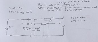
Your 18V AC wallwart followed by the 2 diodes gives -18V, 0, +18V.
This will measure 18V with respect to the 0V live and 36V if measuring from - to + lines.
The filter caps will increase this to 1.4 times ie 25V as they charge to the peak of the AC (50V from - to +).
Check for wiring errors.
You may well need a heat-sink for the regulators.
Power dissipated by the regulator = voltage dropped across the regulator (V in - V out) x current. Though for testing (without a load applied) they should be cool.
this is where I'm confused and should study some electrical engineering. I was thinking I need a neutral wire to give me half wave, otherwise I'd simply have peak to peak of 36v... but that doesn't make sense either.
Will one output on my wire be live and one neutral or is it nominal? And if so how do I correctly identify?
I'm strating to feel well out of my depth here
Will one output on my wire be live and one neutral or is it nominal? And if so how do I correctly identify?
I'm strating to feel well out of my depth here
If you stack two 18VDC power supplies (SM or linear, regulated or not), that will give you the +/- 18V CT that you want. I expect the central engineering issue will be ensuring that the output voltage levels are isolated from the ground reference of the mains. Some devices directly link their circuit ground and/or cases to safety ground. If your CT comes out 18V above safety ground, you could clobber any equipment you connect to your DLCP, or the DLCP itself, lacking proper isolation.
Last edited:
Nannoo,
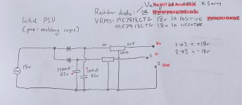
As russc noted, your schematic shows half wave rectification for each voltage rail and it should work, so check for wiring errors.
You noted on your schematic a zener diode as a alternate to the rectifier diodes. That is incorrect. A zener diode will not work. You need to use rectifier diodes. Did you use zener diodes?
You mentioned sparks. Were you making connections with the power on? Hopefully not.
As russc also noted, half wave rectification requires more capacitance to smooth the rectified wave form.
Attachments
You can stack supplies just like you stack batteries. It's not sketchy. Same idea. Any supply will conform to whatever ground reference you assign to it. Just make sure that all your ground references are to the same potential (ie earth or safety ground).hi tgreese,
is stacking two power supplies a better engineering solution? It sounds sketchy but I don't know it that's my lack of education!
Hi all,
Picture is attached. Hope this is clear what I'm trying to do, I looked at the recommended PSU and understand that it says it can be used with an AC wall wart, but still confused over how we achieve that if it requires 3 input rails??
I'm keen to learn how to make these though as I'd like to make some opamp based active filters next year and will need to make psu's for them.
Read the P05 article in post #3 where Rod explains the use of a AC wall wart to achieve split rails.
- Home
- Amplifiers
- Power Supplies
- Trying to build a +/- 18V power supply for hypex DLCP, please help