I recently modified my PSU used for a Class A power amp (-+23VDC and 1.5A bias). I made these modifications:
- removal of softstart NTC at primary side of transformer (it was running too cold)
- change from Schottky diodes to standard 35A bridges (to get stable and less voltage drop over diodes)
- use a mains sinus re-generator to get perfect sine and very low mains impedance (< 8 mohm) and also to get a stabilized AC (230 VAC).
The changes has caused that my DC rails are very stable and my DC offset of amp is stable at 2 mV and it stays there over time.
The PSU has CRCLC filtering and when I use a DMM set to AC the rails just shows 0.0 mV so I have very little noise. However I noticed using REW software that I got some 150 Hz / 250 Hz / 350 Hz / 450 Hz peaks which was not visible before modifications. My 50 Hz and 100 Hz peaks are below 110 dB when I output about 3W at 1000 Hz into 6.8R load resistor. The 150 Hz / 250 Hz / 350 Hz peaks are just below 100 dB. So nothing to worry very much about. I am just interesting in knowing how these peaks are generated as I assume they must be 50 Hz harmonics? ....but my 50 Hz noise peak is very low so how can 150 Hz / 250 Hz be higher?
I guess if I introduced a small resistor just after the diode bridge it would limit the charge current very much and then also maybe remove the noise peaks. Increase of the R in CRC could probably also make a difference. But first I would like to know if others has seen something similar and know how they are generated?
The wirings are almost same before / after modifications but higher change current will introduce more magnetic coupled noise. So these 150 / 250 Hz may be magnetic coupled noise rather than electric coupled noise.....which are probably mostly 100 Hz noise from remaining ripple.
First congratulations on such a low noise floor , I love linear power supplies and linear/analog power amps .
At a guess it could be an artifact of your diodes in recovery/switching mode as I have seen the sharp points on a scope in ripple .
In any case have a read of stack exchange website for professionals for some comments-
power supply - How can I observe rectifier switching noise? - Electrical Engineering Stack Exchange
Thank you for the link. Interesting to read.
Are you the Duncan that has designed "PSU Designer II" software?
The old Schottky diodes modules I used had both snubber and a cap across the AC. C's was 100 nF as far as I remember and R was 10 or 100 ohm. 35A bridges has no snubbers. My IEC inlet is an EMI filter module rated for 2A.
I will try to do some experiments.
Some additional information for my setup.
- my amps are mono blocks
- large chassis with low noise toroid far away from amp
- last C in CRCLC filter close to amp board
- my mains has no PE in my living room outlets but amps are build as there was
- my chassis ground is close to IEC inlet and IEC PE and toroid static shield is connected to that point
- I have defined my signal Gnd on last C's in CRCLC and has a wire from last C's to chassis ground point and is connected via a NTC to have a "lift" from chassis
I wonder if chassis PE connection and signal Gnd to chassis could be two different points so I could have a shorter wire from last caps to chassis?
I want to try to see what happens with 150/250 Hz noise peaks if I short the NTC to chassis (so my signal GND has direct chassis connection) and also if I remove it or use a capacitor instead.
The re-generator I use has its chassis connected via the PE in outlets so my amp chassis will be connected so if re-generator puts any noise on chassis I will get this noise also on my amp chassis. I will try to isolate PE from re-generator so I don't have it connected to amp chassis (remember I have not PE in out mains outlets anyway). I can see if it has any effect on REW noise measurements.
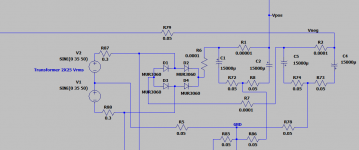
I made some simulations of the Power Supply of an amplifier some years ago.
According to these, the 100 Hz is the strongest one, but its harmonics at 200 Hz, 300 Hz, 400 Hz etc are very close to the 100 Hz peak.
The important is that, as you can see in the FFT of the positive output of the power supply (attached photo), there is nothing in 150 Hz, 250 Hz etc, 350 Hz, etc.
So probably what you see, it is due to some Ground Loop problems of the power transformer of the amplifier with the measurement setup or some electromagnetic coupling to the measurement cables or similar things.
Attachments
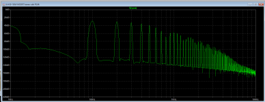
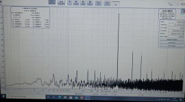
My distortion profile looks like this in the moment.
50 and 100 Hz is ok low.....but 150/250/350/450 is a bit strange......and 250 Hz has the highest peak. They are still below -100 dB and %THD and %THD+N are also quite similar so overall noise is not a big problem. I just wonder where these 150/250 etc......peaks originate from.
The amp is a class A without any global NFB. PP Mosfet output stage.
Attachments
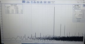
There is a switch on the re-generator so I can switch from re-generator power to just filtered power and if I do that the picture looks a bit different. The 150/250 Hz peaks are smaller and 350/450 almost gone. With non-re-generated power there are more impedance in the mains and the sine has flat tops so cap charge current will be less.....
Attachments
Ok, my DIY measurement system is not a prof. system. It is Focusrite 2i2 and REW software on a laptop. Then a homemade box that converts from speaker banana plug in to RCA out and a pot so I can reduce the signal to the Focusrite input.
It seems everything I try on the PSU I can only provoke 100 Hz and hamonics and 50 Hz I can reduce by use of mu-metal screening. The 150/250 etc.....they just stay stable. I am about to belive that they occur inside the amp circuit and are not direct PSU related......but I might be wrong......
It seems everything I try on the PSU I can only provoke 100 Hz and hamonics and 50 Hz I can reduce by use of mu-metal screening. The 150/250 etc.....they just stay stable. I am about to belive that they occur inside the amp circuit and are not direct PSU related......but I might be wrong......
The bridge rectifier of the power supply cannot produce 50 Hz, 150 Hz, 250 Hz and above harmonics.
It can only produce 100 Hz, 200 Hz, 300 Hz, etc.
So probably what you have, it is due to some Ground Loop problems of the power amplifier with the measurement setup or some electromagnetic coupling to the measurement cables.
It can only produce 100 Hz, 200 Hz, 300 Hz, etc.
So probably what you have, it is due to some Ground Loop problems of the power amplifier with the measurement setup or some electromagnetic coupling to the measurement cables.
You are probably right.
Now I have assembled everything and connected preamp to mono blocks.
With DMM at speaker out when amp is just in "idle" I measure 0.0 mV AC.
I hear no noise in woofer and midrange speaker with ear as close as possible to speaker units. Only tweeter I can hear a little "sshhyyy" with ear very close (I have 94 dB speakers). So I think I am ok and ready for some music.
To make correct measurements is an art in itself......
I know from an earlier 300B tube project that 3 mV hum at speaker out is audible at listening position and 0.5 mV is audible with ear very close to woofer. 0.1 mV is inaudible and was my goal in that project.
There is a small detail I have not mentioned in the CRCLC PSU.
The CRC part is a separate PCB and is meant to be a standalone PSU. I have then added the LC part. But on the CRC PCB there is installed a 1k bleeder resistor across the C in the CRC. So a small current will go there. Could this cause 150/250/350 Hz harmonics?
The CRC part is a separate PCB and is meant to be a standalone PSU. I have then added the LC part. But on the CRC PCB there is installed a 1k bleeder resistor across the C in the CRC. So a small current will go there. Could this cause 150/250/350 Hz harmonics?
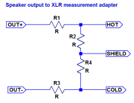
You should not be using an unbalanced connection for amplifier --> interface input - I'd suggest upgrading the interface box. Here's a universal balanced attenuator suited for both bridged and SE outputs:Ok, my DIY measurement system is not a prof. system. It is Focusrite 2i2 and REW software on a laptop. Then a homemade box that converts from speaker banana plug in to RCA out and a pot so I can reduce the signal to the Focusrite input.
R1 = R3, R2 = R4.
Resistor ratio has to be chosen based on output levels to be covered and maximum accepted input level as well as input impedance. For starters, you can try R1 = 22k || 22k, R2 = 330R (1/4 W metal film). This should be good to at least 100 wpc when using the microphone input, more with a 2nd/3rd generation 2i2. You have plenty of input level control range on the interface, you shouldn't generally require more than a fixed attenuator.
I'd suggest putting an XLR output (male) on the interface box. Then XLR --> XLR cabling will permit using the mic-in, while an XLR --> TRS cable would use the less sensitive line-in instead if you ever run into input level limits.
Attachments
Last edited:
When I used Schottky diode modules I had less noise below 1 kHz. I used 15 A Cree types. But these gave me other problems like quite large and a bit unstable feed forward voltage drop so one rail could go up and down 0.5V or so which caused my DC-offset of the amp to be unstable. Now it is very stable using standard 35A bridges. I wonder if same form factor exists with Schottky diodes?
I was surprised that when looking in data sheet that feed forward voltage drop can be quite large on Schottky diodes as they are advertised to have very little forward drop?
I was surprised that when looking in data sheet that feed forward voltage drop can be quite large on Schottky diodes as they are advertised to have very little forward drop?
- Status
- This old topic is closed. If you want to reopen this topic, contact a moderator using the "Report Post" button.
- Home
- Amplifiers
- Power Supplies
- 150 Hz / 250 Hz / 350 Hz noise in linear PSU