I've been experimenting with DMOS since SY got me started with "His Majesty's Noise" RIAA preamplifier.
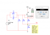
It seemed to me that one could self-bias a DMOS and use it as a current sink. Sweeping from 10Hz to 10MHz and measuring group delay, you can quickly determine whether the power supply/regulator is stable.
The IXYS IXTU02N50D has Ciss of 120pF. The gain plot uses IXTU02N50D, not the DN2540 shown which is 200pF.
Attachments
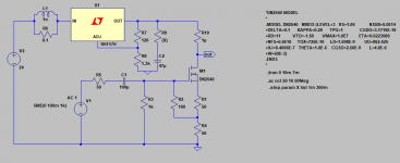
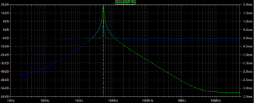
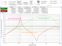
Here's an example, if a bit extreme -- an LM317 for which the DMOS current sink is drawing 24mA. A 47uF Panasonic Aluminum Electrolytic on the output pin (brown-orange trace) is close to being stable but a 10uF polycarbonate (violet trace) isn't.
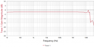
Q is over 5! No output cap on the LM317, it's stable but the impedance stinks.
I used an ancient Tek P6022 current probe with 134 amplifier for the current measurement. The 6022 falls off below 2kHz so the curve was standardized to a 1 ohm non-inductive resistor.
Well, I think it's pretty neat!
Q is over 5! No output cap on the LM317, it's stable but the impedance stinks.
I used an ancient Tek P6022 current probe with 134 amplifier for the current measurement. The 6022 falls off below 2kHz so the curve was standardized to a 1 ohm non-inductive resistor.
Well, I think it's pretty neat!
Attachments
I dont know your current and power requirements, however if you decide you want to dissipate significant energy, you may want to look at the IXYS L2 series of mosfets as they have extended SOA.
Conventional wisdom would suggest a opamp + mosfet combination, but in my experience this is rather hard to keep stable. I eventually got it stable in my regulators, check out the LM7322 its supposed to have good phase margin when loaded with capacitance. but there is a catch, this is only at RL=2.2K for example, so its wise to load up the output a bit with a resistor to ground or to VCC depending on the exact opamp.
You can get around fancy compensation networks by just taking the a LM358 or TL072 and slapping a LH0002 buffer or a discrete component replacement part in the feedback loop, and trim the entire circuit for overshoot with a cap trimmer.
In principle, you do not need to pass the stimulus through the current sink: normally, a VNA is sufficiently sensitive to make the measurement directly (unless you venture into the sub-milliohm region).It seemed to me that one could self-bias a DMOS and use it as a current sink. Sweeping from 10Hz to 10MHz and measuring group delay, you can quickly determine whether the power supply/regulator is stable.
You can then use a "dumb" current sink, eliminating issues of bandwidth, linearity, etc.
Of course, the ports of the VNA need to be properly protected.....
- Status
- This old topic is closed. If you want to reopen this topic, contact a moderator using the "Report Post" button.