Simple truth is that we don't need that even with the fastest and highest energy eating phono preamps as they are class A.
Thanks for your insight! I had the same thought regarding Class A. In theory, transients shouldn't affect the power supply, but I always test my theories. I plan to build several designs to see if there is any difference in sound for any reason. I also plan to build +5V supplies of the same designs for a USB DAC. Thanks again!
One point is the slew rate required from the opamp in a regulator. That slew rate requirement is minuscule. The output of the opamp which drives the pass device will never change more than a few 10's of mV, 100mV tops.
100mV change at 20kHz is a slew rate of 0.026V/us ...
Jan
100mV change at 20kHz is a slew rate of 0.026V/us ...
Jan
3 years ago i used to test very expensive, precise(three decimals precision), high power(4kw) smps, around 100khz switching frequency and all the op-amps(about 20 pcs per board ) used there were opa2227 ( around 2V/us slew rate).All the power sources we built (up to 300kV/65 kVA) used the same op-amp and the test for the 300kV/65kVA supplies was to short circuit the output for 300 times, at 100kV, 200kV and 300kV...All power supplies made by that company used a 2.3 V/us op-amp for sensing the currents and voltages change...The capacitors would be the ones to handle all the trouble there, not the op-amps.
Last edited:
@Safesphere - you can try this one too
VRDN: bipolar regulator PCB for line level ckts: ±11V to ±20V @ 1.5A with "De-Noiser"
VRDN: bipolar regulator PCB for line level ckts: ±11V to ±20V @ 1.5A with "De-Noiser"
Hello safesphere,
I think if I were in your shoes, I might buy a power transformer with 18VAC or even 20VAC secondaries. Then I think I would probably build a cascade of two voltage regulators in series. There's plenty of voltage headroom to do this: 18VAC + Schottky rectifiers gives 24VDC raw. Let the first regulator have 2V in-to-out and let the second regulator have 4V in-to-out. Then: 24V --> reg1 --> 22V --> reg2 --> 18V
The only objective of the first ("upstream") regulator is to reduce ripple and create a much cleaner supply for the second ("downstream") regulator. Now, for the second regulator, you can apply whatever nifty circuits you like, secure in the knowledge that they will operate in a clean(er) environment.
And you get an extra 40-70dB of PSRR at the mains and 2Xmains frequencies.
You can also install RFI filtering and even ferrite bead suppression, before each of the two regulators.
_
Attachments
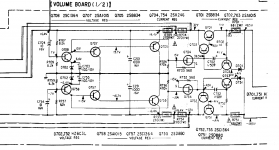
A friend of mine is restoring a Sony TA-ax6 amp and its phono preamp supplied with +-16.4 v derived from +-24v derived again from the main +-32 regulator aimed at supplying the first stages of the power amp, and i saw it's power supply idea like an interesting one, especially because you can supply any type of phono preamp with it and very similar idea with this one: https://www.diyaudio.com/forums/power-supplies/359652-fine-ic-voltage-regulators-25.html#post6348373
Attachments
Last edited:
Hello safesphere,
I think if I were in your shoes, I might buy a power transformer with 18VAC or even 20VAC secondaries. Then I think I would probably build a cascade of two voltage regulators in series.
With so much great advice here, I plan to start with building 2 or 3 different designs to see if any of them sounds better. I can use the same transformer/rectifier to compare different regulators. Then I can put them in series like you've suggested and see if this makes any difference in my system. Than you for the idea!
@Safesphere - you can try this one too
VRDN: bipolar regulator PCB for line level ckts: ±11V to ±20V @ 1.5A with "De-Noiser"
Thanks! Is the board available for purchasing?
With so much great advice here, I plan to start with building 2 or 3 different designs to see if any of them sounds better.
That is the real diy spirit! Good for you!
Jan
that is exactly what you DON'T need with a phono preamp.
Well, to make the scratches etc as "silent" as possible, it needs to handle them swiftly and without distorsion...
//
Hi safesphere, Interesting range of P/Supplies to choose from. What phono amp & cartridge will you be using for your trial.
Cheers
My phono prreamp is the original first Rega Aria MM/MC
I should be getting soon one of the good models of Lyra
The lowest output impedance and fastest regulator is in the diyaudio store:
Jan
Hello Jan,
I have bought the boards for your regulator and I have a quick question. There are ten 120uF caps on the BOM. Can I replace them with either 100uF or 220uF without negatively affecting performance? If I can, which of them (C1-C10) should be 100uF and which 220uF? And which must stay 120uF? Thank you so much!
Alex
- Status
- This old topic is closed. If you want to reopen this topic, contact a moderator using the "Report Post" button.
- Home
- Amplifiers
- Power Supplies
- +/- 18V Low Noise Fast Transient Supply???