I hope I am posting this in the correct forum. My logic is that it is a power supply issue I am trying to resolve first. If this should move to analog sources please let me know.
I have a Sony PS-X600 turntable that I purchased back in 1982. This is a direct drive table with a Biotracer arm (motorized). The arm moves erratically shortly after powering the turntable on - it works correctly for about 10 to 30 seconds. The arm position is determined by LEDs shinning through slits to photo detectors which count the slits to know the arm position.
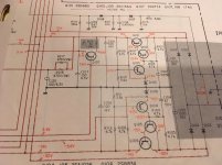
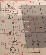
Before working directly on that issue, I thought I would measure voltages in the power supply (schematic below). If the voltages are off it could affect the LEDs and photo detectors. Mostly the voltages are as shown on the schematic. However, +-30 VDC is really +24 and -26 VDC. Given this issue, I thought I should address the power supply first. I note that the +-30 VDC is derived from a 50 AC secondary off the transformer coupled to a bridge recitifier (D101-D104) and two 1000 mF capacitors. My plan was to replace the diodes and the capacitors to get back to the +-30 VDC. I have several 1N4004RLG diodes and I am wondering if they will work. Since the power supply is only driving motors and digital circuitry I assume it is not as demanding as for a preamp or amp. For the capacitors I was planning on using Nichicon Mouser part number 647-UPW1H102MHD1TN 1000 mF 50 VDC.
I am also planning on replacing all the other electrolytics in the power supply. I was going to use Nichican UPW for most of the caps and Kemet film caps for the two .47 mF 50 VDC capacitors.
Should I also consider replacing the transistors in the power supply? If so how can I find substitutes since the original parts are no longer available? I can find cross reference listings but I don't know which parameters are most important. And will the 1N4004RLG work for diodes D107 and D108?
Thanks in advance for any help.
I have a Sony PS-X600 turntable that I purchased back in 1982. This is a direct drive table with a Biotracer arm (motorized). The arm moves erratically shortly after powering the turntable on - it works correctly for about 10 to 30 seconds. The arm position is determined by LEDs shinning through slits to photo detectors which count the slits to know the arm position.
Before working directly on that issue, I thought I would measure voltages in the power supply (schematic below). If the voltages are off it could affect the LEDs and photo detectors. Mostly the voltages are as shown on the schematic. However, +-30 VDC is really +24 and -26 VDC. Given this issue, I thought I should address the power supply first. I note that the +-30 VDC is derived from a 50 AC secondary off the transformer coupled to a bridge recitifier (D101-D104) and two 1000 mF capacitors. My plan was to replace the diodes and the capacitors to get back to the +-30 VDC. I have several 1N4004RLG diodes and I am wondering if they will work. Since the power supply is only driving motors and digital circuitry I assume it is not as demanding as for a preamp or amp. For the capacitors I was planning on using Nichicon Mouser part number 647-UPW1H102MHD1TN 1000 mF 50 VDC.
I am also planning on replacing all the other electrolytics in the power supply. I was going to use Nichican UPW for most of the caps and Kemet film caps for the two .47 mF 50 VDC capacitors.
Should I also consider replacing the transistors in the power supply? If so how can I find substitutes since the original parts are no longer available? I can find cross reference listings but I don't know which parameters are most important. And will the 1N4004RLG work for diodes D107 and D108?
Thanks in advance for any help.
Attachments
Thanks for the quick response.
The +- 30 VDC supplies the turntable motor and the regulators in the power supply. The motor is working correctly and locks at speed. But when I made the measurement, the motor was not running, so I don't think it is loading down the +-30 VDC line. I will go ahead and replace the caps. Will the 1N4004RLG diodes work in the bridge rectifier and should I replace them?
The +- 30 VDC supplies the turntable motor and the regulators in the power supply. The motor is working correctly and locks at speed. But when I made the measurement, the motor was not running, so I don't think it is loading down the +-30 VDC line. I will go ahead and replace the caps. Will the 1N4004RLG diodes work in the bridge rectifier and should I replace them?
Thanks for the quick response.
The +- 30 VDC supplies the turntable motor and the regulators in the power supply. The motor is working correctly and locks at speed. But when I made the measurement, the motor was not running, so I don't think it is loading down the +-30 VDC line. I will go ahead and replace the caps. Will the 1N4004RLG diodes work in the bridge rectifier and should I replace them?
Diodes rarely fail, and if they do, you wouldn't get ANYthing voltage-wise.
You'd get a blown fuse.
So leave them alone.
Still a Problem
I have replaced the caps in the power supply. All of the voltages are very close except the +- 30 VDC. With the motor board plugged in I get +23.9 and -25.3. If I unplug the motor board I get -29.2 and +15.9. The motor board is the only load on the +-30 VDC line other than it supplies other ICs in the power supply. The motor board is also supplied +-14 VDC. The power supply actual voltages are -14.4 and +14.6.
I don't know how to interpret these results. I would normally assume there was a problem with the diodes making up the bridge rectifier. But since there is no blown fuse does that mean they are still good? And how does connecting the motor board bring the voltages close together? I would guess that there is some draw on the +-30 VDC that increases the plus voltage and decreases the negative voltage. But again, I don't know what that means in terms of where the problem lies.
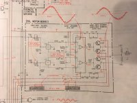
I have attached the portion of the schematic showing the motor board. The +-14 volts powers the logic part of the circuit and the +-30 volts powers the motor. The motor seems to work correctly and drives the turntable at the proper speed.
Any help with next steps is appreciated.
I have replaced the caps in the power supply. All of the voltages are very close except the +- 30 VDC. With the motor board plugged in I get +23.9 and -25.3. If I unplug the motor board I get -29.2 and +15.9. The motor board is the only load on the +-30 VDC line other than it supplies other ICs in the power supply. The motor board is also supplied +-14 VDC. The power supply actual voltages are -14.4 and +14.6.
I don't know how to interpret these results. I would normally assume there was a problem with the diodes making up the bridge rectifier. But since there is no blown fuse does that mean they are still good? And how does connecting the motor board bring the voltages close together? I would guess that there is some draw on the +-30 VDC that increases the plus voltage and decreases the negative voltage. But again, I don't know what that means in terms of where the problem lies.
I have attached the portion of the schematic showing the motor board. The +-14 volts powers the logic part of the circuit and the +-30 volts powers the motor. The motor seems to work correctly and drives the turntable at the proper speed.
Any help with next steps is appreciated.
Attachments
After doing some research and thinking about my results I am back to thinking there is a diode problem. The positive rail is 1/2 of the required 30 volts which could that mean that D101 or D102 is open and therefore I am only getting one half of the wave rectified. But why does plugging in the motor board raise the positive voltage and lower the negative voltage?
I am going to pull and test the diodes tomorrow unless someone has a better idea.
I am going to pull and test the diodes tomorrow unless someone has a better idea.
...rail is 1/2 of the required 30 volts which could that mean ... I am only getting one half of the wave rectified....
Half the diodes is rarely half the voltage.
IIRC, half the diodes is usually "same or none". In the FWB, voltage does not change 1/10th Volt (but the surviving diode may quit soon). In most voltage doublers, loss of one diode give no output.
I suspect, and this is only speculation, due to this unit not being on my bench, that it's possible that one of the transistors driving the motor could be leaking or bad.
It's possible that the motor might still run, but with increased loading of the power supply.
Check the junctions of all 4 of them.
It's possible that the motor might still run, but with increased loading of the power supply.
Check the junctions of all 4 of them.
Sounds like a bad transformer center tap to ground connection.But why does plugging in the motor board raise the positive voltage and lower the negative voltage?
Mona
I have tested all of the diodes using my multi meter on the diode test setting and got theses results: Forward measure 0.462 on all 4 diodes. Reverse measure D101 and 102 1.64. D103 and 104 1.56. When I measure a known good diode (1N4004RLG) I get .578 forward measure and out of range on reverse measure. According to the multi meter user manual, if I don't get a reverse out of range measure, I have a leaky diode. Based on my measurements I have 4 leaky diodes. Does that make sense and should I replace them?
I measured the transformer center tap resistance to ground and it is 0.1 Ohm. So it is good unless there is a problem internal to the transformer.
I have tested all of the transistor junctions on the motor board, but I don't know how to interpret the results.
This is what I have found:
Q301 E -0.09 Q303 E -0.14
Q301 B -0.62 Q303 B -0.68
Q301 C 24.6 Q303 C 24.6
Q302 E -0.09 Q304 E -0.14
Q302 B -0.62 Q304 B -0.68
Q302 C -25.9 Q304 C -25.9
If there is a problem with the motor board, that is going to be a much more difficult fix since I will need to borrow an oscilloscope in order to be able to make the adjustments on that board if I replace any active components. Plus, getting to the board will be challenging as the service manual is not clear on how everything fits together.
However, there is still an issue with the power supply since with the motor board disconnected the positive rail is too low at 15.9 VDC. Am I right in assuming the active components in the power supply are all OK since all of the voltages other than the positive rail are very close to their targets? Where do I look next?
Before replacing diodes, I was measuring PS voltages with the motor board unplugged. Something happened, either I touched two pins at once not realizing it, or the motor board being unplugged caused something to fail. Or possibly it was close to failing and finally did.
With new diodes I am now seeing +27 and -27.8 at the diodes. The negative voltages all look good, but Q101 appears to have failed. I get 27.8 at the collector, 2.1 at the base and 1.5 at the emitter. Q1 is an SD880. I found on AudioKarma that Toshiba remanufactured it as a KSD880. I also found another reference that the KSD880 would be a suitable replacement IC.
I have attached datasheets for both the SD880 and the KSD880. I think that the KSD880 will work, but would like an expert opinion.
Also is it likely that any of the other positive voltage regulator transistors were damaged? Q102 and Q103 are 2SC1364 and Q107 is 2SD774. I have attached their datasheets as well. Not sure about substitutes.
- Status
- This old topic is closed. If you want to reopen this topic, contact a moderator using the "Report Post" button.
- Home
- Amplifiers
- Power Supplies
- Sony PS-X600 Turntable Power Supply Problem