Hi noNo, not afterCan you see why?
if the voltage drop across the cap multiplier is constant i will have just to add this V drop when setting the voltage with the IC reg stage.
If the cap multiplier has no self noise, while the IC regulators have it, i would put it at the end as a last filter
If not the self noise of the IC stage will reach the circuits to be supplied unfiltered.
Anyway I really have no clue about how big is this self noise of the IC regulators The datasheet report only the psrr of the IC regulators
I will check better
Found something and i am reading
What Linear Regulator Chips Have the Lowest Noise Figures?
Last edited:
The volt drop is one thing. The whole point of a regulator is to provide a stable voltage that doesn't change in response to load variations.
A cap multiplier would be very poor in that regard. Also you have the volt drop to contend with.
Most voltage regulators like the 78/79 series work best with just a small cap at the output for stability (see the data sheets for details). Large caps destroy the transient response of the regulator.
A cap multiplier would be very poor in that regard. Also you have the volt drop to contend with.
Most voltage regulators like the 78/79 series work best with just a small cap at the output for stability (see the data sheets for details). Large caps destroy the transient response of the regulator.
Thanks but i am mainly interested in low consumption class A circuits so the current draw should stay constant. And while at the output of a IC regulator is not recommended to put big uF after a cap multiplier i could put thousands of uF without any issue i guess ... a sea of capacitance that should take care of any peak of current drawThe volt drop is one thing. The whole point of a regulator is to provide a stable voltage that doesn't change in response to load variations
yes as i said above ... the response to transients will be taken care by the last big cap after the cap multiplier. Those caps could be placed also locally on the preamp board. Like 1000-2200 uF per rail ... it is a lot.A cap multiplier would be very poor in that regard. Also you have the volt drop to contend with.
Most voltage regulators like the 78/79 series work best with just a small cap at the output for stability (see the data sheets for details). Large caps destroy the transient response of the regulator
But after understanding all these issues about IC regulators i wonder if a discrete regulator with zener would be a more hassle free option. Together with a cap multiplier ... before or after ?
Last edited:
Hi thanks ! i was thinking to that. But then someone told me how noisy are zeners ...A resistor and a Zener diode. That will do
it never ends 
It was just joking as you think a lot (good!) but lack basic knowledge. Of course IC regulators are better than a resistor/Zener diode combo. Of course are ultra low noise regulators (and not their 40 year old cousins) the way to go certainly when you lack basic electronic skills. Of course you should not limit everything to just 1 application. Etc.
As answers are opinions in many cases you could use your time to design a PCB for the PSU you want. Include all necessary stuff on 1 board, add extra pads for options and experiment in practice. You could add pads for both LT4320/MOSFETs and also Schottky diodes, you could add CLC filtering as many don't because coils are expensive, you could choose footprint of a few modern regs so your designs a bit more universal, you could add various footprints of various sizes filter caps (tip: snap in caps are nearly always better). You could make it RF proof while the air is full of RF. You could show the design here and the progress you make and get useful directions. In the end you could end up with a real PSU.........
Cap multipliers are no substitute for regulators.
Last edited:
It was just joking as you think a lot (good!) but lack basic knowledge. Of course IC regulators are better than a resistor/Zener diode combo. Of course are ultra low noise regulators (and not their 40 year old cousins) the way to go certainly when you lack basic electronic skills. Of course you should not limit everything to just 1 application. Etc.
As answers are opinions in many cases you could use your time to design a PCB for the PSU you want.
Include all necessary stuff on 1 board, add extra pads for options and experiment in practice. You could add pads for both LT4320/MOSFETs and also Schottky diodes, you could add CLC filtering as many don't because coils are expensive, you could choose footprint of a few modern regs so your designs a bit more universal, you could add various footprints of various sizes filter caps. Etc.
Cap multipliers are no substitute for regulators
Hi thank you very much again. I have decided to start with LTSpice. I understand that reality can be quite different from ideality ... but i believe in simulation a lot. I have been hugely impressed by the sim result of a little more than basic cap multiplier. I see that a very cheap tip142t with its hfe=1000 can be a great cap multiplier. And i could put another stage (before the cap multiplier) to regulate the voltage with a zener.
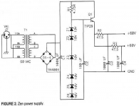
Years ago i was playing with a Bride of Zen preamp by Nelson Pass
Its power supply uses zeners followed by RC filtering (schema attached)
I think i could use the cap multiplier (CM) instead of the RC filter and get a greater psrr ? that CM will take care also of the noise from the zener diode ... hopefully
And the preamp was quite silent after all.
I would prefer the tip142t to the tip29 for its much higher hfe.
I would use just one zener ... even if i read that higher voltage zeners are noisier I have great expectations on the CM ... really great after seeing the results from sim Unbelievable psrr
Attachments
Last edited:
Believing is done in church. I never simulated anything but built stuff and it got me there. Of course simulation can save time (which is the goal after all) but IMHO the knowledge should be in the head not in a program and experience is gained by doing stuff and measuring what you have created.
Believing is done in church. ..... IMHO the knowledge should be in the head not in a program and experience is gained by doing stuff and measuring what you have created.
Amen.
Hi point taken ... i should have said trust. I trust math and i trust also measurements.Believing is done in church.
this is not a little thing. In a matter of second you can change some parts value and see if the circuit is stable or not ... its distortion ... calculate its gain Zout ... for me stability is the very key ... i do not understand at all the concept of stability.I never simulated anything but built stuff and it got me there. Of course simulation can save time (which is the goal after all)
And this is a very big problem for me. I had a little integrated from Rotel and a decent headphone amp with too much Vgain ... i wanted to use the HP amp as line preamp so i tried to reduce the Rotel gain changing the FB resistor The amp was buzzing ... i put an hand on the heatsink and the sking remains attached ... what a pain ... the heatsink was unbelievably hot
I knew after that i had made the amp unstable ... and burned some parts with some smoke as well
i would leave a sw to do the rough job ... then of course the knowledge of the designer is fundamental to get a nice resultbut IMHO the knowledge should be in the head not in a program and experience is gained by doing stuff and measuring what you have created
List extended:
Ratio of the white noise and the DC voltage for various voltage and current references:
85A2 (glow discharge): 648.8 nV/sqrt(Hz) and 85 V, so 7.633E-9 Vref/sqrt(Hz)
LM723 (Zener / avalanche diode): 86 uV from 10 Hz to 10 kHz at 5 V output voltage, so 172.1E-9 Vref/sqrt(Hz)
LM317 (bandgap): 0.003 % of Vout from 10 Hz to 10 kHz, so 300.2E-9 Vref/sqrt(Hz)
uA7805 (bandgap): 40 uV from 10 Hz to 100 kHz at 5 V, so 25.3E-9 Vref/sqrt(Hz)
LT1236 (buried Zener reference): 2.2 uV from 10 Hz to 1 kHz at 5 V, so 13.98E-9 Vref/sqrt(Hz)
LT3081 (unknown, presumably bandgap): 5.7 nA from 10 Hz to 100 kHz at 50 uA, so 360.5E-9 Iref/sqrt(Hz)
LT3042 (unknown, presumably bandgap): 6 nA from 10 Hz to 100 kHz at 100 uA, so 189.7E-9 Iref/sqrt(Hz)
TL431 (bandgap): 125 nV/sqrt(Hz) at 2.495 V, so 50.1E-9 Vref/sqrt(Hz)
Of course it's not entirely fair comparison since the 85A2 uses 467.5 mW in its recommended operating point, far more than the LT1236 or the references of the LM723, LM317 and uA7805. Besides, when the noise is specified from 10 Hz to x Hz, there will be some 1/f noise included.
I built and measured a bandgap reference based on the 1960's Electronics Letters principle. It reaches 6.005E-9 Vref/sqrt(Hz), see https://www.diyaudio.com/community/threads/return-to-zero-shift-register-firdac.379406/#post-6881707 posts 20, 35 and 36.
Marcel, I recall that there is a difference between in which brand produced/produces LM723. Some are nothing special and some are very quiet.I built and measured a bandgap reference based on the 1960's Electronics Letters principle. It reaches 6.005E-9 Vref/sqrt(Hz), see https://www.diyaudio.com/community/threads/return-to-zero-shift-register-firdac.379406/#post-6881707 posts 20, 35 and 36.
Same goes for TL431 now often produced by strange brand names in the Far East.... Also for 78xx/LM317 that are made by various manufacturers. Something one will not see when using LT3045 for instance. So it is IMO important to mention brand and exact typename and maybe even a datecode.
Example: if I would use the list I would assume LM723 to have 86 µV of noise. In practice I have found versions that are always below 5 µV. I am not alone in this.
https://dg4rbf.lima-city.de/Rauschmessungen am LM723.pdf
Last edited:
I'm doing a VFET front end card using the super deluxe AS-431 from Diodes Inc. They redesigned the TL431 and got much better performance. Check out their "Stability Boundary Conditions" graph on page 8 of the manufacturer's datasheet (LINK) . It's a vast improvement over TI and OnSemi.
I dont know if its already been mentioned in this thread but there are now much better linear regulators than the venerable 78xx/317, the LT304x series for example. They work on a different
principle to the older 3 terminal regs which used a fixed voltage reference which is then amplified up by the error amplifier to give the required o/p voltage. This means that the reference voltage noise is also amplified up with increasing regulator voltage and the regulator,s psrr falls off with frequency as the amplifier does.
The LT304x use an adjustable voltage reference formed from a current source working into a bypassed variable ( to set the o/p voltage) resistance. This is a very low noise voltage reference, mainly the johnson noise of the resistor. A unity gain buffer then converts the reference voltage to the o/p voltage. The already very quiet reference voltage is not amplified up with increasing o/p voltage and the frequency response of the unity gain buffer amp can be much wider that with an amplifier with gain. If you look at the data sheet you see that this results in both ultra low noise and a high psrr out to a few mhz. In my experience it works very well and I believe there is now a neg voltage version.
I would imagine the topology could be replicated with discrete components but I dont see how doing that would improve upon its performance.
People have tried using LT304x regulators for ES9038Q2M dac AVCC regulators. Why? Because the specs look so impressive. Those same people sometimes later decide to try a Jung regulator or try an opamp buffer and find the dac sounds better that way. IIRC Topping uses opamp buffers as AVCC regulators for the latest version of their D90 dac, which uses an ESS PRO dac chip. Maybe part of it is that IC manufacturer marketing guys have a lot of say about what goes into a datasheet. They put in what they think will help sell parts, and may sometimes leave out info they hope nobody will notice. Does ESS explain Hump Distortion in their datasheets? No. Why not? They hope you won't notice, would be my guess. Another example: the book, The Art of Electronics, has info about opamps that isn't included in datasheets. Do the opamp manufactures have that information? Of course they do, but they leave it out of the datasheets. Bottom line in this case: LT304x are good for some things alright. Maybe not so good for other things.
What sounds better and what is better is a can of worms. LT3042/3045 are fine regs and better than 78xx/LM317.
What sounds better really is thin ice and one goes into territory of effect generators, H2 generators, preference etc. where it sometimes can be seen that simply mediocre performers are liked. For that reason Korg Nutube devices gain popularity In DC power supplies a few parameters dominate the final results and when the device that is used with the "better" PSU does not perform well then maybe that device itself is not designed correctly. Designing only by ear is a never ending story.
What sounds better really is thin ice and one goes into territory of effect generators, H2 generators, preference etc. where it sometimes can be seen that simply mediocre performers are liked. For that reason Korg Nutube devices gain popularity
In DC power supplies a few parameters dominate the final results and when the device that is used with the "better" PSU does not perform well then maybe that device itself is not designed correctly. Designing only by ear is a never ending story.
Last edited:
Markw4, I don't think you can equal the parameters of LT3042/3045 by building a discrete regulator in terms of quality/cost/board space. As much as I like discrete designs... these are just very good regulators.
Anecdotical evidence that these are not performing well for AVCC of ESS DACs should be complete with measurements WHY they supposedly don't perform OK. Are these new designs with LT regs on the PCB or existing devices with separate LT reg PCBs with wiring? There are many factors that can have influence on perceived results.
Anecdotical evidence that these are not performing well for AVCC of ESS DACs should be complete with measurements WHY they supposedly don't perform OK. Are these new designs with LT regs on the PCB or existing devices with separate LT reg PCBs with wiring? There are many factors that can have influence on perceived results.
Last edited:
- Home
- Amplifiers
- Power Supplies
- Are you really fine with IC voltage regulators ?