I always thought that John Curl's approach to voltage regulation for preamp circuits, was brilliant. However it does possess characteristics which some people really don't like
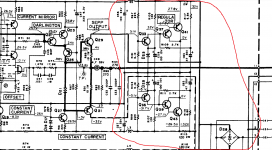
Curl's idea is to connect two, carefully chosen, voltage regulators in series. RawDC ---> Regulator_1 ---> Regulator_2 ---> DC Output
Regulator_1 is a plain ordinary series regulator made from a low cost IC: LM317 or LM337. Its job, its only job, is to reduce mains ripple by 66dB.
Regulator_2 is a shunt mode regulator, built with discrete transistors. It consists of a constant current source, driving an active constant voltage shunt.
Eureka! Notice that Regulator_2 draws a constant current from Regulator_1. Another way to say this is: Regulator_1 sees a constant load current. The ideal and perfect arrangement for best operation of Regulator_1.
Eureka! Notice that Regulator_1 provides a constant output voltage. Another way to say this is: Regulator_2 sees a constant input voltage. The ideal and perfect arrangement for best operation of Regulator_2.
Eureka! Notice that the cascade has wonderful line rejection (aka PSRR aka ripple rejection). 66dB from Regulator_1 and plenty more from Regulator_2.
Eureka! Notice that the audio circuits (the "loads" upon the regulator) are fed from a shunt regulator, so they get all the benefits of shunt regulation that Walt Jung and many other researchers have praised.
My conclusion: I like it. I think it's brilliant.
_
1. It requires a higher "raw DC" input voltage. In most cases this means a different power transformer with a higher AC output voltage. So instead of a [2 x 15VAC , 10VA] transformer, Curl's regulator needs a [2 x 18VAC , 10VA] transformer. If you are familiar with the line of transformers made by Antek, this means you buy "AN-0118" instead of "AN-0115". They are the same size and the same price.
2. It uses at least 2x as many electronic components and at least 2x as much area on a printed circuit board. These additional components also add to the parts cost of the final audio equipment
3. It contains twice as many carefully designed circuits and offers twice as many opportunities for the assembler or the copy-and-paste "re-designer" to make mistakes which degrade the sonics
4. It requires you to know in advance, the total current drawn from the regulated supply voltage, by all loads.
5. It dissipates more heat inside the chassis and draws more current from the AC mains
Curl's idea is to connect two, carefully chosen, voltage regulators in series. RawDC ---> Regulator_1 ---> Regulator_2 ---> DC Output
Regulator_1 is a plain ordinary series regulator made from a low cost IC: LM317 or LM337. Its job, its only job, is to reduce mains ripple by 66dB.
Regulator_2 is a shunt mode regulator, built with discrete transistors. It consists of a constant current source, driving an active constant voltage shunt.
Eureka! Notice that Regulator_2 draws a constant current from Regulator_1. Another way to say this is: Regulator_1 sees a constant load current. The ideal and perfect arrangement for best operation of Regulator_1.
Eureka! Notice that Regulator_1 provides a constant output voltage. Another way to say this is: Regulator_2 sees a constant input voltage. The ideal and perfect arrangement for best operation of Regulator_2.
Eureka! Notice that the cascade has wonderful line rejection (aka PSRR aka ripple rejection). 66dB from Regulator_1 and plenty more from Regulator_2.
Eureka! Notice that the audio circuits (the "loads" upon the regulator) are fed from a shunt regulator, so they get all the benefits of shunt regulation that Walt Jung and many other researchers have praised.
My conclusion: I like it. I think it's brilliant.
_
Attachments

Thanks for the information. It means, I was mistaken. Probably, I learnt it from a book written by F.A. Wilson when I was 16 years old many many moons ago. The series was "Elements of Electronics". The intended readers for this series were 'inquisitive adolescents asking awkward questions'.dreamth said:anything between 5.1 and 6.2 will do the job.
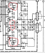
they used CRD in the past for zener regulation:
Last edited:
Curl or Jung Didden?I always thought that John Curl's approach Curl's idea is to connect two, carefully chosen, voltage regulators in series. RawDC ---> Regulator_1 ---> Regulator_2 ---> DC Output
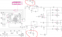
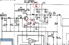
The previous post had some parts of a schematic that used a +-20v dc series reglator after another series +-24v reglator in order to spply a phono preamp...
i understand the beneffits of Jung Didden reg yet it looks like they are made for circuits with no PSRR of their own...
some very advanced phono preamps used some of these circuits, but their lowest noise stages had it all sorted out straight from their own internal current sorces...
Attachments
i have a successful semi-professional recording soundcard using Linear technology switching regulators for +-12v of all dacs and op-amps inside and the switching chip is actually designed in the 90's while the soundcard was made in 2016, best sales on Amazon for a sondcard in 2017 and still in production for a higher price than in 2017 when i purchessed mine...Audient ID22
I see no benefit to going crazy and complex over power supply designs, particularly to power line-level circuits, and RF stages.
A simple cap-multiplier filter before an LMxxxx regulator, and voila, a nice, clean, stable, noise-free DC output is the result.
I've been building supplies like this for years, with no ill effects.
A simple cap-multiplier filter before an LMxxxx regulator, and voila, a nice, clean, stable, noise-free DC output is the result.
I've been building supplies like this for years, with no ill effects.
Mark,
In addition to Mark’s description in his best products JC also uses carefully constructed cap multipliers at the local load with selected low noise Toshiba jfets for phono stages or Hitachi mosfets for line level (and resistors matched to the idss of the jfet) and film caps (usually Relcaps) to bypass the output to load. Non magnetic components are preferred.
In addition to Mark’s description in his best products JC also uses carefully constructed cap multipliers at the local load with selected low noise Toshiba jfets for phono stages or Hitachi mosfets for line level (and resistors matched to the idss of the jfet) and film caps (usually Relcaps) to bypass the output to load. Non magnetic components are preferred.
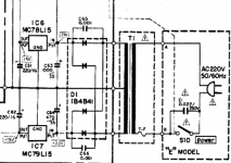
if yo don't like having no regulator at all yo can simply go with the L version of 78/79xx regulators and an additional rc filter for the most sensitive parts.OP-amps have their own PSRR which isn't really bad most of the times.
Attachments
30 years ago, in another audio forum where you used a VT100 terminal to participate, we discussed such power supply strategies. One guy said he deliberately injected pulses on the power supply lines to test the PSRR of a popular audio opamp; said he couldnt hear a thing until the pulse was raised to "ridiculous" levels. They also were designing and discussing discrete shunt regulators at the time.
Unsure why no one uses a power op amp for a linear regulated voltage. At Intel, we had these to-220 devices with an amp continuous output, 1 GHz bandwidth. That could have some flat impedance looking back into it - at least through the audio range.
Since it's an amplifier, it should have both series (source current) and shunt (sink current) capabilities. (I forgot to take any with me, when they threw out all the entire engineering component stock from the power supply lab as they let us all go, then closed the place for good)
Last edited:
I would hazard a guess that the winning PCB voltage regulator from the Linear Audio "shootout", costs about 1/3rd as much, fully stuffed and soldered, as a TO-220 thru hole packaged, 1 ampere rated opamp with 1 GHz bandwidth. But I don't know for sure, I can't find any such opamps myself.
Unfortunately, I cant remember the P/N. I do recall the company that made the device went out, and we had our "lifetime supply". (We were going to use them as big FET drivers for step current generators, but went with a different design) I'm sure there's other more reasonable power op-amps to choose from these days - unless there's something technically wrong with the idea in the 1st place.
Ginetto - All discrete power supplies for high Voltage or high current applications makes sense as there are not many IC regulators to choose from. But for a pre-amp I think you are wasting your time. After all, what do you think is inside those IC regulators? A bunch of transistors and passive components! Just much smaller than discretes…. How do I know? I work for one of those companies that make regulators.
I'm not saying that there aren't better and worse regulators for audio. Look around and you will find regulators for almost any specific task. Low drop-out, low wideband noise, high PSRR, you name it. Look around enough and you will surely find much better regulators than you are likely to be able to design yourself.
I'm not saying that there aren't better and worse regulators for audio. Look around and you will find regulators for almost any specific task. Low drop-out, low wideband noise, high PSRR, you name it. Look around enough and you will surely find much better regulators than you are likely to be able to design yourself.
As far as I always knew, since I was a sixth form student back in 1985, Zener diodes are the foundation of voltage references. If you want more precision, supply a reference Zener diode through a constant current source and use a buffer amplifier to avoid loading it.
Bandgap references are also used a lot: a VBE of a transistor plus the amplified voltage difference between the VBEs of transistors running at different current densities. The LM317 already uses a bandgap reference and most more modern regulators do the same. Unfortunately the usual bandgap implementations are quite noisy.
i am attaching the schematic i have in mind to overcome the fact the zener diodes are not good voltage reference
The LM acts only as a voltage reference and drives the bjt base that actually provides voltage to the load
The LM is not providing voltage to the load at all
That circuit is worse than the regulator alone. It adds a non-linear and relatively low gain device to what it a very low impedance regulator.
Jan
To answer the original question: that depends on the circuit that is to be supplied. In most cases cheap IC voltage regulators work well enough, but if it is some low noise circuit with a limited PSRR or a DAC reference, I would insert a brute-force low-pass filter to get rid of the regulator's noise, or use a very low noise IC regulator like an LT3042 (which gets its low noise by brute force low-pass filtering between its reference and the rest), or use some other type of regulator.
If I understood correctly, a bandgap reference can be made from a diode and a resistor connected in series with one end to ground and supplied current by a constant current source. If the resistor has a positive temperature coefficient 'a', then the resistance should satisfy 0.002 = a.R.I, where R is the value of the series resistance and I the constant current. The 2mV/K drop across the diode is compensated for by an equal increase in voltage across the resistor.MarcelvdG said:Bandgap references are also used a lot:
Finally someone making the logical step: how can you speculate about which circuit is best, if you don't say for which purpose?
Look at your circuit, and the power supply requirement. Does it have a high PSRR - then that does not need to be the first priority for the regulator. Is it a circuit that must be very low noise - you probably want to concentrate on a low noise supply too.
And then there is the marketing angle - I'm sure you guys are aware that often designers lay out their PCBs and parts with the beautiful internal pictures that Stereophile will print in mind ;-)
Jan
If I understood correctly, a bandgap reference can be made from a diode and a resistor connected in series with one end to ground and supplied current by a constant current source. If the resistor has a positive temperature coefficient 'a', then the resistance should satisfy 0.002 = a.R.I, where R is the value of the series resistance and I the constant current. The 2mV/K drop across the diode is compensated for by an equal increase in voltage across the resistor.
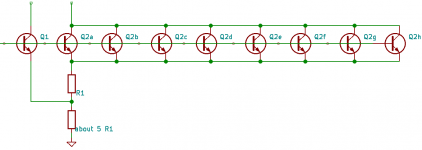
Indeed, but the positive temperature coefficient current itself is derived from the voltage difference between two diodes running at different current densities, and in practice one preferably uses transistors rather than diodes.
A typical bandgap reference could consist of the attached schematic plus a feedback loop that changes the base voltages until the collector current of Q1 equals the sum of the collector currents of Q2a...Q2h and is not zero. Due to the lower current density, the base-emitter voltages of Q2a...Q2h have a slightly more negative temperature coefficient than the base-emitter voltage of Q1. As a result, the currents through the resistors get a positive temperature coefficient, in fact they will ideally be proportional to absolute temperature (PTAT) when the resistors are temperature-independent.
The reason that the circuit is noisy is that you are amplifying a small difference between base-emitter voltages. The emitter resistor R1 is normally the dominant noise source. A much better approach if you want low noise is to use stacks of scaled transistors rather than one scaled pair, but that requires more transistors and more supply voltage.
Attachments
Last edited:
- Home
- Amplifiers
- Power Supplies
- Are you really fine with IC voltage regulators ?