Thanks for the schematic. Do you have figures about the improvements that the 1st discrete regulation stage provides ? this i could do extracting (and eventually replacing) the mains transformer and leaving the existing regulation stage I am still undecided about using some passive DC filtering before the regulation stage First i have to remove the transformerref. to post no.80
Thanks a lot again.
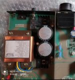
Attachments
If you reverse the order of the stages also, i.e. regulator first,
C multiplier second, you may get 30 dB less noise.
Cheers, Gerhard
In my circuit, it's already free of noise.
Nothing to hear, nothing to measure. (Oscilloscope confirms this)
Using the design I posted, it also lowers and controls the input voltage to the regulators which allows them to run cooler.
In preamps/filters that I've made, the regulators are barely warm at all, driving several opamps.
Changing the transformer solved the problem, the spike and buzz was largely gone. The replacement was the same VA size and physical design, it must have had a/ better quality iron or b/ ran it at a slightly lower magnetization level.
TCD
People who have 100-115VAC mains can do a cute little stunt on their low-VA transformers: If you need "X" volts AC at the transformer output, buy a transformer whose secondaries are "2X" volts AC, and then connect its two primary windings in series as someone in a 230VAC country would do.
Now each of your primaries sees 57.5V AC, reducing transformer core magnetization by a factor of 2. Increasing margin-of-safety against core saturation by a factor of 2.
Yes you have also cut the available VA in half but so what, it's a preamp, how many VA do you actually need? Antek's 25VA transformers are only slightly larger and slightly bigger than their 10VA transformers, for example.
The wiring route from transformer's secondary to rectifying bridge to cap bank carries the HF spurae and spreads EMI pollution.
I keep the bridge very close to the transformer and if possible the caps as well.
If not, I place a common mode choke in series to the distant caps (and twisted wiring).
I'm not suggesting CM choke is a bad thing however most of the noise discussed here from core saturation, diodes etc is predominantly differential.
Regarding transformers, all those I have measured start to saturate at around 70% of their rated main's voltage.
It helps with voltage self stabilisation, but once saturation commences, magnetic flux leakage increases, making the transformer add to the EMI spread.
George
IME they can be over the map - depending on design. Toroidals are more
consistent due to the fact the core is a/ gapless b/ more efficient being predominantly GOSS (grain oriented silicon
steel) so they tend to have quite low magnetizing current until quite near
saturation.
EI cores vary considerably depending on core material and design. Some very old valve amp transformers (and very cheap Chinese transformers)
can have really high magnetization current quite some distance from saturation with commensurate horrible OP waveforms.
TCD
In my circuit, it's already free of noise.
Nothing to hear, nothing to measure. (Oscilloscope confirms this)
That's why you normally measure noise with a spectrum analyzer: it's far more sensitive than a scope, and even then you have to be careful that it is the DUT and not to analyzer that you measure. It can also be done with a high-gain low-noise preamplifier, a filter and an oscilloscope or a high-gain low-noise preamplifier and a sound card.
Same with 'nothing to measure on the scope'. Without knowing what the bandwidth, resolution, sensitivity of the scope is, it doesn't say much.
Jan
Let's conclude that the scope is a new digital model, and the bottom line of the DC readings show a virtual straight line with perhaps a nanovolt of interference, likely from external sources.
And I'm sure a lousy nanovolt isn't enough to even discuss or worry about.
When you look at the ratio of the noise and the DC voltage, they are not bad at all compared to the references used in solid-state voltage regulators:
85A2 (glow discharge): 648.8 nV/sqrt(Hz) and 85 V, so 7.633E-9 Vref/sqrt(Hz)
LM723 (Zener / avalanche diode): 86 uV from 10 Hz to 10 kHz at 5 V output voltage, so 172.1E-9 Vref/sqrt(Hz)
LM317 (bandgap): 0.003 % of Vout from 10 Hz to 10 kHz, so 300.2E-9 Vref/sqrt(Hz)
uA7805 (bandgap): 40 uV from 10 Hz to 100 kHz at 5 V, so 25.3E-9 Vref/sqrt(Hz)
LT1236 (buried Zener reference): 2.2 uV from 10 Hz to 1 kHz at 5 V, so 13.98E-9 Vref/sqrt(Hz)
Of course it's not entirely fair comparison since the 85A2 uses 467.5 mW in its recommended operating point, far more than the LT1236 or the references of the LM723, LM317 and uA7805.
How does the LT3081 compare? https://www.analog.com/media/en/technical-documentation/data-sheets/3081fc.pdf
This is a no measurement.Same with 'nothing to measure on the scope'. Without knowing what the bandwidth, resolution, sensitivity of the scope is, it doesn't say much.
Jan

Let's conclude that the scope is a new digital model, and the bottom line of the DC readings show a virtual straight line with perhaps a nanovolt of interference,
I take it you have not a lot of experience with digital scopes?
Jan
Let's conclude that the scope is a new digital model, and the bottom line of the DC readings show a virtual straight line with perhaps a nanovolt of interference, likely from external sources.
And I'm sure a lousy nanovolt isn't enough to even discuss or worry about.
In the graph of #60, a Toshiba 7805 scores 43 dB above [0 dB = 1 nV/rtHz] noise density,
that is 141 nV/rt Hz. That would be more for a 7815, and even more for a noise
bandwidth that is bigger than 1 Hz. For 100 Hz it would be 1.41 uV.
For 10000 Hz bandwidth, that would equal 14.1 uV.
Noise voltage goes with the square root of BW.
So let's conclude: That is not one lousy nV, that is one lousy regulator.
Last edited:
List extended:
Ratio of the white noise and the DC voltage for various voltage and current references:
85A2 (glow discharge): 648.8 nV/sqrt(Hz) and 85 V, so 7.633E-9 Vref/sqrt(Hz)
LM723 (Zener / avalanche diode): 86 uV from 10 Hz to 10 kHz at 5 V output voltage, so 172.1E-9 Vref/sqrt(Hz)
LM317 (bandgap): 0.003 % of Vout from 10 Hz to 10 kHz, so 300.2E-9 Vref/sqrt(Hz)
uA7805 (bandgap): 40 uV from 10 Hz to 100 kHz at 5 V, so 25.3E-9 Vref/sqrt(Hz)
LT1236 (buried Zener reference): 2.2 uV from 10 Hz to 1 kHz at 5 V, so 13.98E-9 Vref/sqrt(Hz)
LT3081 (unknown, presumably bandgap): 5.7 nA from 10 Hz to 100 kHz at 50 uA, so 360.5E-9 Iref/sqrt(Hz)
LT3042 (unknown, presumably bandgap): 6 nA from 10 Hz to 100 kHz at 100 uA, so 189.7E-9 Iref/sqrt(Hz)
TL431 (bandgap): 125 nV/sqrt(Hz) at 2.495 V, so 50.1E-9 Vref/sqrt(Hz)
Of course it's not entirely fair comparison since the 85A2 uses 467.5 mW in its recommended operating point, far more than the LT1236 or the references of the LM723, LM317 and uA7805. Besides, when the noise is specified from 10 Hz to x Hz, there will be some 1/f noise included.
I dont agree, it can't be a nanovolt. The lowest sensivity of 'average' oscilloscope let be 1 mV (1 mV/cell or 1 mV/10 mm. Ant as we know it can be 2 mV and 5 mV, and even 10 mV). Lets pretend that we can see about one tenth of this, so the minimum visible 'line' (or degree) is about 0.1 mV. This is 100 microvolt but not nanovolt. 100 uV of noise is ok for 'ususal' power supply but a lot for low-noise one.Let's conclude that the scope is a new digital model, and the bottom line of the DC readings show a virtual straight line with perhaps a nanovolt of interference, likely from external sources.
And I'm sure a lousy nanovolt isn't enough to even discuss or worry about.
Last edited:
I take it you have not a lot of experience with digital scopes?
Jan
Incorrect assumption.
I'm a long-time audio/video service tech, now mostly retired.
And posts 116,117,119 are nitpicking at inaudible BS.
Last edited:
wiseoldtech,
technology you publish here is old but not especially wise (sorry couldn’t resist the pun)
Additional transistor and few capacitors + resistors can be put to much more effective use, bringing those old lousy regulators to microvolt noise level and above 100 dB PSRR. Kissed frog doesn’t become a prince, as there are better modern regulators but achieved result is incredibly good. More on this is here:
D-Noizator: a magic active noise canceller to retrofit & upgrade any 317-based V.Reg.
As for the nanovolt noise levels, I doubt anybody could measure them without liquid nitrogen cooled equipment. Standard digital oscilloscopes have internal noise floor greater than 80 uV.
Gerhard is a member with knowledge and excellent equipment for noise measurements so his statements are facts and not an opinion.
- Home
- Amplifiers
- Power Supplies
- Are you really fine with IC voltage regulators ?