You can connect primaries in series with differing loads on multiple secondaries when they share a core. The problem of unbalanced loads and primaries in series applies only to independent transformers. You still need to pay attention to secondary load capability and keep your loading within those limits, but I assume you already know that.
To make it clear before I blow things.
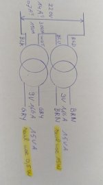
It's possible with this? See pictures.
I dont know if the drawing that i made is ccorrect on primairy side
secundaire side : One end will feed raspberry pi. Other end DAC board
It's possible with this? See pictures.
I dont know if the drawing that i made is ccorrect on primairy side
secundaire side : One end will feed raspberry pi. Other end DAC board
Attachments
Last edited:
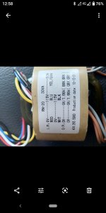
As I understand the marking on the transformer, your diagram is correct.
BUT, just not to harm anything: For a start try the transformer alone with 230Vac at the primary (RED/BLACK) AND A SMALL FUSE (0.2-0.5A) IN SERIES WITH THE PRIMARY! If we misunderstand the marking, the fuse will blow instantly. If the fuse is not blown, check that the secondary voltages are about right (10-15% higher voltage when unloaded).
BUT, just not to harm anything: For a start try the transformer alone with 230Vac at the primary (RED/BLACK) AND A SMALL FUSE (0.2-0.5A) IN SERIES WITH THE PRIMARY! If we misunderstand the marking, the fuse will blow instantly. If the fuse is not blown, check that the secondary voltages are about right (10-15% higher voltage when unloaded).
Last edited:
An externally hosted image should be here but it was not working when we last tested it.
Primary Red and Brown are labelled "0V" so they can be assumed to be the start/beginning of each winding and "should" match your drawing.
In any case, confirm that by wiring them the way you think , secondaries connected to nothing, and plugging primary into mains, with some safety device added.
A small fuse is fine, as suggested by fauxfrench or use a dim bulb limiter with a 25 or 30W filament ,lamp.
If it blinks, fine, if it stays brightly ON, your wiring is wrong and you mustvreverse *one* primary.
I find it quite stupid they did NOT identify secondaries, using same colour for both ends each. (Brown-Brown and Grey-Grey)
IF you will use them completely separate, no big deal, but if wrong phase, in series you may have 0V end to end and in parallel you will burn the transformer.
Russian roulette with 3 bullets in the revolver.

I asume the labelling is correct.
Your drawing doesnt match my 'planned'setup for the secundairy wiring.
In my idea they stay separately. So 2 X 9V (one for pi and one for DAC board).
Primary Red and Brown are labelled "0V" so they can be assumed to be the start/beginning of each winding and "should" match your drawing.
In any case, confirm that by wiring them the way you think , secondaries connected to nothing, and plugging primary into mains, with some safety device added.
A small fuse is fine, as suggested by fauxfrench or use a dim bulb limiter with a 25 or 30W filament ,lamp.
If it blinks, fine, if it stays brightly ON, your wiring is wrong and you mustvreverse *one* primary.
I find it quite stupid they did NOT identify secondaries, using same colour for both ends each. (Brown-Brown and Grey-Grey)
IF you will use them completely separate, no big deal, but if wrong phase, in series you may have 0V end to end and in parallel you will burn the transformer.
Russian roulette with 3 bullets in the revolver.
Primary RED and WHITE are indeed indicated as 0V, so I assume it's correct. Secondary will stay separate so 2 x 9V. Is this possible? current in primary will flow through both windings on the front end, but secondary has different load (Pi board = 2-3 A, DAC = 0,1A)
Primary RED and WHITE are indeed indicated as 0V, so I assume it's correct. Secondary will stay separate so 2 x 9V. Is this possible? current in primary will flow through both windings on the front end, but secondary has different load (Pi board = 2-3 A, DAC = 0,1A)
Sorry, you are right, typed from (poor) memory
 , RED and WHITE are presumed winding start.
 Yes, secondaries can have different loads, no problem.
One can even be fully unused.
Yes, both primaries in series will pass any power required by secondaries; any secondaries will provide its rated voltage (in this case 9VAC) , with current up to rated value (1.66A? ... again quoting from memory because while answering picture is not visible
)Secondary current limitation does not come from core saturation (which allows up to 30VA total) but winding wire diameter.
IF some day you want to join them, series or parallel, test them as I mentioned above and then label them for future use, you can paint a white line (printer correction pen) along "0V" wire, add a small tape label or simply tie a knot with the 0V wire.
You don't want to "blow things " right ?
As you probably live in the EU ( 230V AC ) then if you connected both Primaries in Parallel instead of Series you certainly would "blow something " probably the primary winding's of the transformer under load.
The Primary is your main concern initially , and reversing the winding's start turns isn't a good idea--180 degrees out of phase.
when faced with this kind of an issue we normally use a known good transformer of the same secondary voltage (VA rating does not matter) and connect it to the secondaries. The voltage on the primary will tell you if you got the connection correctly or in danger of blowing things.
For all transformers we get made the physical layout of the wires denotes the correct method of connection, be it primary or secondary.
For all transformers we get made the physical layout of the wires denotes the correct method of connection, be it primary or secondary.
You don't want to "blow things " right ?
As you probably live in the EU ( 230V AC ) then if you connected both Primaries in Parallel instead of Series you certainly would "blow something " probably the primary winding's of the transformer under load.
The Primary is your main concern initially , and reversing the winding's start turns isn't a good idea--180 degrees out of phase.
I got feedback from the seller...he made sure that first winding 0 (RED) - 115 (BLU) and second winding 0 (WHT) - 115 (BLK).
So connecting BLU en WHT would made it suitable for 230V between RED and BLK So it's his responsibility now
...I will make video for him when i plug it in Im also have doubt what happens on the secondary side.
The Pi on 1 winding will have big variation in current flow.
Will this create 'stress'on the transformer and will this noise be transmitted on the other secondary winding? (unstable/high freq noise V and A). Second winding will feed a DAC board so Im after the highest stable V and A)
Last edited:
Before plugging it in test it!
Use an old AC wall wart that output something between 10 & 24 Volts AC as the supply source. Measure all the output voltages and some simple math will tell you if you got it correct.
Great idea...will do...Thanks
I can see why you want to build your own PS for your DAC many are OTT in price , for the record I have a Chord DAC costing over £1000 highly thought of in the UK it runs off a small SMPS but its well smoothed.
No it wont "imbalance" the transformer that different currents output from each secondary if you are that worried about this then Parallel the secondaries to give you double the current output for the same voltage .
First things first go for a VERY high quality rectifier , certainly no cheap block of plastic this will cut down diode "noise " .
This usually means an industrial standard rectifier .
What exactly are you connecting to the AC output of the transformer ?
Give me the type of "regulator " and if the rectifier isn't "critical " for a high quality power supply to a quality DAC then by "regulator " you mean ----SMPS --- right ?
I am talking of a Linear power supply you are talking something else .
Give me the type of "regulator " and if the rectifier isn't "critical " for a high quality power supply to a quality DAC then by "regulator " you mean ----SMPS --- right ?
I am talking of a Linear power supply you are talking something else .
- Status
- This old topic is closed. If you want to reopen this topic, contact a moderator using the "Report Post" button.
- Home
- Amplifiers
- Power Supplies
- How to use 2x 115v transformer on 230v