PCB manufacturing files in the industry standard Gerber format are attached to post #1 of this thread. You can send them off to a PCB fab, yourself. I recommend using the super helpful website
www dot pcbshopper dot com
to help you select a fab, based on price and total wait time. Presto, freshly manufactured VRDN boards delivered right to your doorstep. Depending on how many you order and how many you need for your own hobby pursuits, you may wind up with extra boards left over. This becomes an excellent opportunity to "Pay It Forward" by giving spare VRDNs away to other hobbyists, or selling at breakeven.
_
Last edited:
Power Supply
I am building Wayne's line stage and I need a power supply- I checked into the VRDN boards and it looks like the best price to quantity ratio comes to 14 board which results in $18.80 a board --
Does Anyone still have interest in any boards - I'm glad to sell them for $18.80 or maybe $19.00
I am building Wayne's line stage and I need a power supply- I checked into the VRDN boards and it looks like the best price to quantity ratio comes to 14 board which results in $18.80 a board --
Does Anyone still have interest in any boards - I'm glad to sell them for $18.80 or maybe $19.00
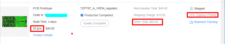
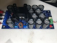
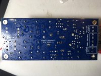
My most recent VRDN order is shown below. I bought 20 PCBs and selected the very fastest shipping option they offered, "DHL Express Priority", which is 3 days from Shenzhen China to my front door in the San Francisco bay area. Total cost was $68.05 for 20 boards, which works out to $3.43 per board. The fab was JLCPCB.
_
_
Attachments
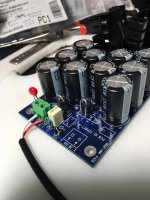
I build a VRDN using a 16VAC Wall Wart. V+ out works perfectly. V- out is dead with no voltage output at all. I have tried it with and without the denoiser jumpers and that makes no difference. I've looked at the boards closely and I don't see any problems with the soldering or with shorts. I'm not quite sure what I should check/replace that would be most likely to cause a total failure of the V- Rail. Any suggestions? Pictures attached.
Attachments
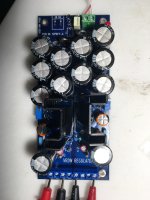
This is the build option for using the VRDN with a wall wart which only has a single secondary. You can see it discussed by Mark in the first post in this thread.The V- side doesn't seem to have an input supply: the screw terminals aren't even soldered
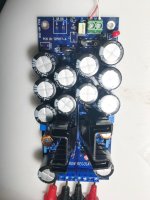
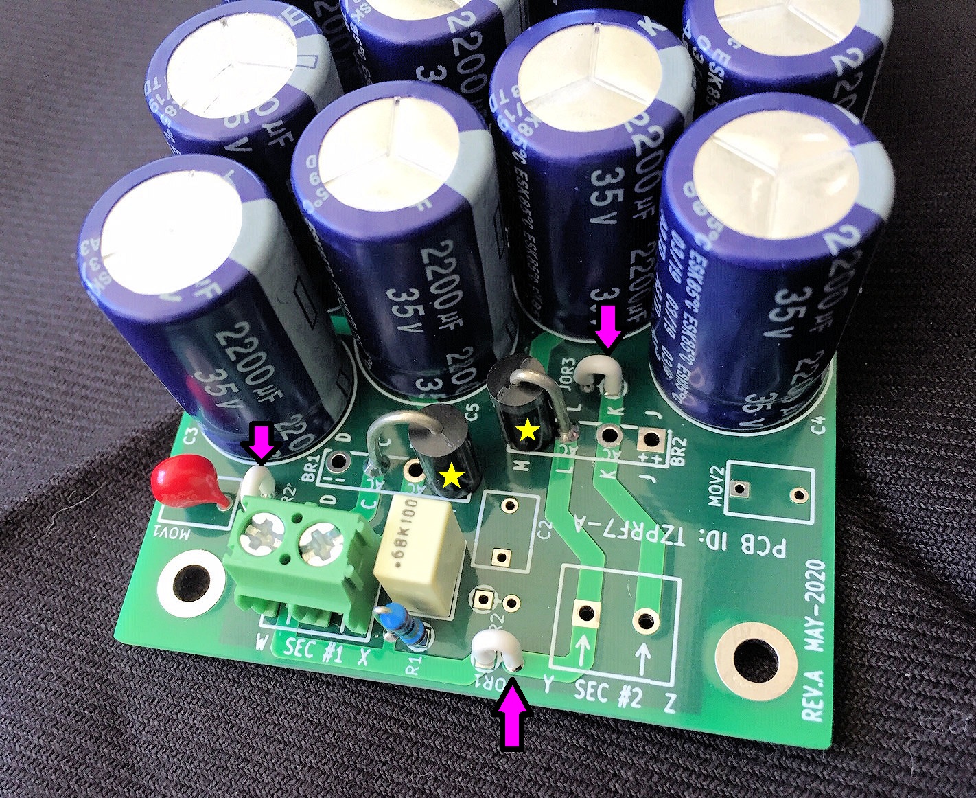
Please take a photo from an angle like this one, so the three jumper wires (arrows) are clearly visible. Also, please make sure that your photo shows the "bands" on the cathode ends of the diodes. This picture doesn't show them very well.
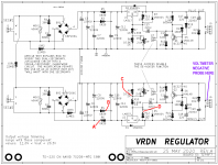
Next, if you stuffed the vertical mount resistors exactly as indicated on the PCB silkscreen graphics, you'll have access to several important circuit nodes via the flying wireloops on the vertical resistors. Please measure the voltages at nodes A, B, C, D and write your measured voltages on the schematic. The fat end of the schematic symbol for vertical resistor, is the abutted end -- the non-flying-wireloop end -- on the PCB. The normal end of the resistor symbol is the wireloop end.
Finally, go to the drugstore and buy a bottle of >90% purity isopropyl alcohol. The one near me sells both 91% and 99%. Also buy a child's toothbrush with soft bristles. Use the toothbrush and IPA to scrub the flux residue off the bottom of your board. Pour about a capful of alcohol on the board, scrub vigorously. Rinse with another 1 or 2 capfuls of alcohol. Repeat 4X. Do the top side too, if it's nasty. You can use a pistol type of hair dryer (cool setting) to dry the board more quickly.
_
Attachments
Here are photos of that end of the board. Even though the butt end of one of the diodes is different from your picture the cathode still goes into L.Please take a photo from an angle like this one, so the three jumper wires (arrows) are clearly visible. Also, please make sure that your photo shows the "bands" on the cathode ends of the diodes. This picture doesn't show them very well.
Next, if you stuffed the vertical mount resistors exactly as indicated on the PCB silkscreen graphics, you'll have access to several important circuit nodes via the flying wireloops on the vertical resistors. Please measure the voltages at nodes A, B, C, D and write your measured voltages on the schematic. The fat end of the schematic symbol for vertical resistor, is the abutted end -- the non-flying-wireloop end -- on the PCB. The normal end of the resistor symbol is the wireloop end.
Finally, go to the drugstore and buy a bottle of >90% purity isopropyl alcohol. The one near me sells both 91% and 99%. Also buy a child's toothbrush with soft bristles. Use the toothbrush and IPA to scrub the flux residue off the bottom of your board. Pour about a capful of alcohol on the board, scrub vigorously. Rinse with another 1 or 2 capfuls of alcohol. Repeat 4X. Do the top side too, if it's nasty. You can use a pistol type of hair dryer (cool setting) to dry the board more quickly.
_
So a little more information. The first time I tried to test the board I kludged up a connection to the wall wart and the positive still tested 16V but nothing on the negative rail and then the wall wart got friend which I attributed to my moving the board around and causing a short where I was attaching to the wall wart. Then with the second wall wart and the proper female plug and I used a dim bulb tester and that was when I got readings on the positive rail but nothing on the negative rail and no fried wall wart.
To try and measure your voltages I removed the dim bulb tester and after a few minutes the wall wart got fried again. Before it died I was able to measure 190mv at R6. Also, weirdly, even though the wall wart was putting out 19 volts not connected to anything it only read 13 volts at the incoming terminal blocks. J1. Positive rail read 16.5 volts before everything died.
I must have a short somewhere on the negative rail that is causing the wall wart to fail when it isn't connected to a dim bulb tester. Might still fail but maybe it takes longer to over heat?
This is getting expensive in wall warts and it will take a couple of weeks to get more. Is there a way of locating the short that doesn't fry wall warts every time?
Attachments
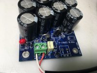
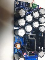
Your 3 jumper wires are installed correctly and your two diodes are also installed correctly.
The fact that the wall wart's output is 19VAC with no load, but drops to 13VAC when connected to the VRDN input terminals, means that VRDN is drawing an abnormally large, erroneously large, current from the wall wart. This could be caused by a short on your PCB.
The first thing I would do, is check to see whether the two diodes behave the same. If they don't, if their behavior is wildly different, then it's likely that the diode on the negative side has probably failed. Since the positive supply seems to work, it's likely that the diode on the positive side is okay.
I'd set my DVM to the lowest range of Ohms measurement (not continuity "beep" testing, Ohms measurement) and attempt to measure the resistance of the diode on the positive side. Do this once (red probe to cathode, black probe to anode) then swap the probes and do it again (black probe to cathode, red probe to anode). Write down the results. Now measure the diode on the negative side with the same procedure. Write down the results. Did the two diodes behave the same, or not?
To avoid destroying more wall warts, you could install a 3 watt, approx 100 ohm resistor in series with one of the wall wart wires; it doesn't matter which one. Now even if VRDN is a total dead short, your wart only provides (16.5 / 100) = 0.165 amperes; 2.8 watts. That is unlikely to burn out your wart.
You can create a 3W 100R resistor by connecting twelve 1.2K, 1/4 watt resistors in parallel. Or whatever you have in your parts box, do series/parallel calculations to get 100 ohms and >3 watts.
If you happen to own a variable voltage "lab" DC power supply with variable current limiting, it's pretty likely that you can use that instead of a wall wart, to troubleshoot your faulty VRDN. The power supply protects itself, while you protect the VRDN. You pick a current-limit number low enough (suggestion: 40mA) to ensure you don't accidentally melt your VRDN. More info on that after you post a photo of your DC power supply.
Finally: please verify that the IC voltage regulator on the negative side is part number LM337, middle digit is "3". Maybe there is a parts stuffing mistake?
Thanks for the suggestions Mark. I have an auto ranging multimeter which hopefully doesn't make a difference. Both diodes measure the same. Positive to Anode 3.14K Ohms. Positive to Cathode 9 M Ohms.
Voltage Regulators are on the correct sides.
I am going to have to put this on hold for a couple of weeks but I will give your suggestion with resistors a try.
Thanks.
Voltage Regulators are on the correct sides.
I am going to have to put this on hold for a couple of weeks but I will give your suggestion with resistors a try.
Thanks.
Good afternoon folks! I'm beginning to plan my Wayne's 2018 LS build and, obviously, I need a PSU.
This one is, obviously, one of the most appealing options! Still, purchasing more than two boards to ship to my country makes very little sense. Purchasing more than two and starting a group buy where I can send from Ecuador really will pick no-one's interest (if I'm mistaken, please let me know!!!).
Does anyone have one or two boards I can purchase from you? Mark, do you have some leftover boards you can sell? (or charge it to those $100 you owe me on League of Frightened Men quote ).
).
No, but seriously, if anyone is planning a print, I would buy two boards and pay shipment to Miami (I don't require shipping to Ecuador, I'll import the boards from there).
Thanks for any trouble this causes,
Rafa.
This one is, obviously, one of the most appealing options! Still, purchasing more than two boards to ship to my country makes very little sense. Purchasing more than two and starting a group buy where I can send from Ecuador really will pick no-one's interest (if I'm mistaken, please let me know!!!).
Does anyone have one or two boards I can purchase from you? Mark, do you have some leftover boards you can sell? (or charge it to those $100 you owe me on League of Frightened Men quote
).No, but seriously, if anyone is planning a print, I would buy two boards and pay shipment to Miami (I don't require shipping to Ecuador, I'll import the boards from there).
Thanks for any trouble this causes,
Rafa.
Thanks jimk04! Our national postal office went bankrupt and we are facing year-long waits on packages with more than 60% of them lost forever. So I would need to purchase and send to the US and have a specialized currier send things over from Miami. It is expensive, but it works. I just need to group several things together for the shipment to make sense. But, anything that comes my way, is probably stuck here forever.
So, while purchasing 20 boards for $70 bucks would make perfect sense for someone in the US and then just re-sell those remaining 18 boards at coast to help the community, for me that would leave me with 20 boards for $90 (after shipping to Ecuador) and with no real useful way to re-distribute those other 18 boards. I would be essentially paying $90 for two boards and some nice additional decorations.
Thanks for the offer! One would be enough to drive the WLS. still you would be shipping from the UK to the US for me to import to Ecuador... that sounds like a lot of trouble / cost. If no one local to the US has some, I'll take you up on the offer and contact you to see how to resolve payments and stuff. Thanks!
Rafa.
@Mark and Friends,
I have a nice Mouser Project with almost all the components listed by Mark, included the A.2 additional components detailed in #198.
There are a couple of replacements and some non-stocked items, so I wanted to ask if my substitutions are OK, listed here from "least sure" to "almost sure" they work.
If all these substitutions work, I just need to secure a suitable transformer. If not, then I would need to start making alternate plans.
Thanks so much for any insight and thoughts on the substitutions. If they are OK, I could share the Mouser project with the community to help other builders if that is OK with Mark and if there is use in that.
Thanks again,
Rafa.
I have a nice Mouser Project with almost all the components listed by Mark, included the A.2 additional components detailed in #198.
There are a couple of replacements and some non-stocked items, so I wanted to ask if my substitutions are OK, listed here from "least sure" to "almost sure" they work.
- 512-BC33740TA Not stocked anywhere, and no other BC337 with the "40" extension except for this one from Taiwan Semiconductor: 821-BC337-40-A1. Unfortunately there is no 327 equivalent from the same brand, so I'm unsure if mixing-and-matching works for this part? The name in Mouser would suggest that the BOM part is 45V while my substitution is 50V, but the datasheet would suggest that Vcbo is 50V, but Vceo is, indeed 45V. But I really know nothing about this, so... I'm really lost as if this is a valid substitution and only for the BC337 at that, since the BC327 would be from a different brand. Any info would be highly appreciated.
- 647-UVR1V221MPD1CJ Not in stock. I plan to substitute it for 647-UKL1V221MPD1TD. They are from a different series: proposed BOM is from the UVR series which is (as per a photo that Mark shared elsewhere) the 'standard' line, substitution shares almost all characteristics (except length, but probably not an issue?), but it is from the UKL series, which is a "Low leakage Current" type, not sure if this has any effect that would be detrimental to this system. Other options to substitute with had "low impedance" characteristics, so not sure which is the 'worse' option between low leakage and low impedance and if this affects this particular circuit.
- 603-MFR-25FBF52-220R Not in Stock. There is a 603-MFR25SFRF52-220R which is a "small" version of the same resistor, much smaller in size, smaller lead diameter, but maybe that is not really crucial? But I may be missing some important characteristic here, so I thought I'd check.
If all these substitutions work, I just need to secure a suitable transformer. If not, then I would need to start making alternate plans.
Thanks so much for any insight and thoughts on the substitutions. If they are OK, I could share the Mouser project with the community to help other builders if that is OK with Mark and if there is use in that.
Thanks again,
Rafa.
Last edited:
The TO-92 bipolar transistors in the VRDN circuit, were directly lifted from Elvee's "De-Noiser" as explained in post #1 of this VRDN thread. The De-Noiser is separately discussed in a big thread, HERE.
Several builders of Elvee's De-Noiser circuit have observed (and posted scope photos of) oscillation. Not what you want in a voltage regulator. It's a relatively sensitive circuit, and I don't recommend straying too far from a known-to-work, known-not-to-oscillate implementation.
When I built my VRDN prototypes a year ago, the BC327-40 and BC337-40 transistors that Elvee specified, were plentiful and cheap. So that's what I used and indeed that's all I have ever used in VRDN. I have no personal experience with any other transistor type in the De-Noiser portion of VRDN.
Elvee did mention that his De-Noiser circuit will remove even larger amounts of noise, when you substitute the ZTX851 and ZTX951 transistors instead of the BC's. Both of these ZTX parts are in stock (at least, they are today!) at Mouser. I recommend you visit his thread and ask about this substitution: is it suitable for beginners, do any other component values need to be changed in the VRDN+De-Noiser, does he have another transistor substitution that he likes even more, etc.
If you do substitute the ZTX transistors, observe that they have a different pinout than the BC transistors on the VRDN PCB. So you may have to bend the transistor leads & rotate the transistor bodies, to make them work correctly in the VRDN board.
Another thing you can do is ask Elvee how much performance is lost, if you decided to use the -25 suffix parts instead of the -40 suffix parts. Both the BC327-25 and the BC337-25 are in stock at Mouser today, and naturally they match the footprints on the VRDN PCB. Maybe the performance degradation is very slight. You can always order the -40 suffix parts and swap them in, as soon as Mouser has them back in stock. You could even put the ZTX transistors on this future order, and try them (with scrambled lead legs!!) too.
For the 220uF 35V electrolytic with 5mm lead spacing and 10mm diameter, I recommend following the advice in spreadsheet cell 18J of VRDN's Detailed Parts List: "select for lowest cost". For me that would be 80-ESW227M035AH9AA which is cheap AND rated for 105 degrees C AND is in stock at Mouser USA. But just about any LS=5, DIA=10, 35V, 220uF cap will do the job.
For the 220 ohm resistor I recommend you stick with 1% metal film types, either 220 ohms (E6 series of standard resistor values) or 221 ohms (E96 series of standard resistor values). Some people insist upon always buying Dale E96 resistors; it's their fetish. I'd recommend any of these 19 resistors, all of which are in stock today at Mouser USA (MOUSER LINK)
edit- here is a SUPER handy table that shows the E6, E12, E24, E48, E96, E192 series of standard electronic component values, in a color-coded and easy to understand chart: LOGWELL TABLE
_
Last edited:
- Home
- Amplifiers
- Power Supplies
- VRDN: bipolar regulator PCB for line level ckts: ±11V to ±20V @ 1.5A with "De-Noiser"