No good, they emailed me with $14.00 per board because of 4 layers
I still need boards.
Happy New Year.
PCBShopper – A Price Comparison Site for Printed Circuit Boards is a price comparator (for pcb-production), recommended by great Mark Johnson...
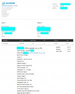
Where do I get the correct Gerber file?
Post #1, last item?
Since there is very little noise on the output of the VRDN, would it make sense to add a 5volt regulator off the output to provide for a digital power line? Would this mess up the output impedance of the VRDN, does it make sense?
I'm currently using a low noise DC2DC converter to get my +-5Volts I need.
I'm currently using a low noise DC2DC converter to get my +-5Volts I need.
This is possible of course, but would you really want to mix the analog and digital grounds via a (common) power supply returns? If it's a DAC you are talking about and its USB stage has an isolated input/ground, then this approach will simply not work because the grounds, once isolated, will be commoned together at the power supply.
However, if you use a SECOND VRDN as pre-regs, purely for a dedicated LT3045 / LT3094 voltage regs (for example), positioned very close to where they are needed...
However, if you use a SECOND VRDN as pre-regs, purely for a dedicated LT3045 / LT3094 voltage regs (for example), positioned very close to where they are needed...
I haven't calibrated an LNA myself but I have read a few posts on diyAudio over the past few years, written by people who were doing that very thing. They seem to prefer using the Johnson-Nyquist "thermal noise" of a 1% metal film resistor, since this noise is (a) determined by basic physics and not by good/bad circuit design; and also (b) accurately known in advance.
Most of them choose a 1K resistor to do their calibration, which gives a noise voltage density of 4.07 nanovolts per root Hertz, as shown in the Wikipedia article excerpted below.
_
Most of them choose a 1K resistor to do their calibration, which gives a noise voltage density of 4.07 nanovolts per root Hertz, as shown in the Wikipedia article excerpted below.
_
Attachments
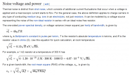
I haven't calibrated an LNA myself but I have read a few posts on diyAudio over the past few years, written by people who were doing that very thing. They seem to prefer using the Johnson-Nyquist "thermal noise" of a 1% metal film resistor, since this noise is (a) determined by basic physics and not by good/bad circuit design; and also (b) accurately known in advance.
Most of them choose a 1K resistor to do their calibration, which gives a noise voltage density of 4.07 nanovolts per root Hertz, as shown in the Wikipedia article excerpted below.
_
I will look into the calibration of the LNA. At this point, I'm trying to see if my entire test set-up is in the ball park. I'm feeding the AC from one rail into the LNA, then into and ADC, Focusrite Solo, and using either REW or ARTA to view the RTA. I'm getting a noise floor of about 108dB with both programs. Just wondering if I'm in the ballpark.

Thank you to thompsontechs  and ZUM911 for reporting the same problem that I had hit and never had the skills to troubleshoot back in early Sept (post #128). I took a look and you'll never guess which 337 regulator I am using (you probably guessed it).
VRDN: bipolar regulator PCB for line level ckts: ±11V to ±20V @ 1.5A with "De-Noiser"
I never tested my board with the denoiser connected and added the jumpers today and was pleasantly surprised to see that 'it had fixed itself' until I started reading through the rest of the thread today and saw all the investigation that had transpired.
Thank you Mark J for your support!
I didn't have any 22nF caps so I took 2 more of the 6.8 and soldered them to the pads of the existing C16 for a total of 20.8nF now and the neg rail goes all the way to -21V where it was stuck at -15.5V previously.
Time to order some new caps and maybe some new regulators while I'm at it.
and ZUM911 for reporting the same problem that I had hit and never had the skills to troubleshoot back in early Sept (post #128). I took a look and you'll never guess which 337 regulator I am using (you probably guessed it).VRDN: bipolar regulator PCB for line level ckts: ±11V to ±20V @ 1.5A with "De-Noiser"
I never tested my board with the denoiser connected and added the jumpers today and was pleasantly surprised to see that 'it had fixed itself' until I started reading through the rest of the thread today and saw all the investigation that had transpired.
Thank you Mark J for your support!
I didn't have any 22nF caps so I took 2 more of the 6.8 and soldered them to the pads of the existing C16 for a total of 20.8nF now and the neg rail goes all the way to -21V where it was stuck at -15.5V previously.
Time to order some new caps and maybe some new regulators while I'm at it.
Update: I pulled the TI LM337 and found a tube of Fairchild 337. Swapped one in and removed the extra 6.8nF caps (back to original 6.8nF instead of 20.4nF) and not stuck at -15.5V anymore.
If it's worth anything meaningful, the voltage did bounce a bit between about -19.x and -20.x volts a bit with the denoiser disconnected ... does that imply some oscillation still going on or is that a ghost in the machine? It's completely stable with the denoiser connected.
If it's worth anything meaningful, the voltage did bounce a bit between about -19.x and -20.x volts a bit with the denoiser disconnected ... does that imply some oscillation still going on or is that a ghost in the machine? It's completely stable with the denoiser connected.
Put one together tonight and will hopefully test it out tomorrow. I had a terrible time soldering some of the leads, though: ones that are connected to ground. I am guessing this is because the ground planes are so big they act as heat sinks. Anyone else experienced this? What's the best strategy? I increased the heat after a while but am reluctant to set it too high lest I damage the parts...
I never tested my board with the denoiser connected and added the jumpers today and was pleasantly surprised to see that 'it had fixed itself' until I started reading through the rest of the thread today and saw all the investigation that had transpired.
The way I read your post, it looks like you installed jumpers today to enable the denoiser. Installing jumpers disables the denoiser, according to the first post in the thread.
With the jumper installed I was able to get -20V but without the jumper I could only get about -15.5V. Adding the extra caps at C16 let me get past -20V with and without the jumper installed and now with the Fairchild LM337 and without the extra caps, it's also able to get to -20V (just a bit beyond but not to -21.0V). When I power it on the readings on both the + and - bounce around a bit but stabilize after about 20 seconds.
With the jumper installed I was able to get -20V but without the jumper I could only get about -15.5V. Adding the extra caps at C16 let me get past -20V with and without the jumper installed and now with the Fairchild LM337 and without the extra caps, it's also able to get to -20V (just a bit beyond but not to -21.0V). When I power it on the readings on both the + and - bounce around a bit but stabilize after about 20 seconds.
According to the schematic on the first post denoiser is used without the jumper installed. That explains the bouncing (over- and undershoot of the denoiser). It also explains why you had only -15.5V earlier. Denoiser was probably oscillating.
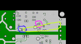
Hi!...the denoiser is not optimally placed, it's right in the high current path. It should be isolated from the high current loop...
...and sorry, but I'm not sure to understand which solution you suggest: Do you mean that e.g. C17+Side and R15+Side side should have a "dedicated" and as short as possible connection to the LM317 Output pin?
Thanks for clarifying,
Winfried
I marked on the photo where the regulator is, and where the denoiser transistor is, and also the current path between the regulator and connectors. As you see the denoiser is right in the path of the current flow. Ideally the denoiser should be isolated from it.
Attachments
- Home
- Amplifiers
- Power Supplies
- VRDN: bipolar regulator PCB for line level ckts: ±11V to ±20V @ 1.5A with "De-Noiser"