6.8 nF ---> 22 nF is not a gigantic change; just 10dB . It may suggest that your VRDN was just barely over the line and into "you must oscillate" territory just a wee bit. Very pleased to hear that it's now doing what you want it to do. 33nF would probably be safer still but why fix it some more if it ain't broke no longer.
Maybe this will provoke a prolonged "okay buy WHY??!?" discussion since some but not all boards oscillated.
Maybe this will provoke a prolonged "okay buy WHY??!?" discussion since some but not all boards oscillated.
The 317 and 337 have been designed to look like mirror images of one another, but that's not the case, and the 337 is in fact the evil twin of the 317: it is more demanding, more touchy, and its structure is different. It requires a higher no-load current, and it is known to oscillate in some legit situations, when it shouldn't.
A known fact since decades. The early 79xx also had this. It depends on brand too for a part. That is why the power LED usually was connected to the LM337. Omitting the input cap lead to oscillation in many cases just like an undefined state with strange voltages at startup (or even complete latchup). There are negative regulators that don’t exhibit this phenomenon ") I also recall shortlived adjustable versions of 78xx and 79xx both having these issues.
I also recall shortlived adjustable versions of 78xx and 79xx both having these issues.
I was taught then to avoid LM337 (NOT LM317) and use simple discrete circuits or the forgotten XR4195 when a symmetric PSU was needed to supply opamps. Thankfully progress gave better negative regulators.
I also recall shortlived adjustable versions of 78xx and 79xx both having these issues. I was taught then to avoid LM337 (NOT LM317) and use simple discrete circuits or the forgotten XR4195 when a symmetric PSU was needed to supply opamps. Thankfully progress gave better negative regulators.
Last edited:
Mark, since you are busy revising stability issues, I think you could have a look at the output series resistor (R22).So the next thing I did was perform some simulations. I found that the circuit became EVEN MORE STABLE in simulation, if the series RC compensation network was changed. Instead of (6.8 nanofarads SERIES 15 ohms), I found that (33 nanofarads SERIES 1 ohm) was even more stable.....
I have the feeling that, combined with the ESR of the cap, it could result in a largish value, which would be problematic if a new mask revision of the 337 has a larger loop gain than earlier versions.
A large value has the advantage that the regulator will tolerate otherwise insane combinations of external output caps (something some members love to indulge in), because it will damp almost anything, but when the regulator is on its own, it could cause instabilities.
Note that having symmetrical components for the - and + sections may look intellectually and aesthetically speaking satisfying, but since the 317 and 337 are in fact very different different regulators, there is no contraindication opting for different values.
Overcompensating the 317 will do no harm, but it will reduce the available correction gain at high frequencies, and reduce the effectiveness of the denoiser at those frequencies.
10nF is reasonable tradeoff, and for the 337, 22nF should be OK, maybe with a revision of the OP cap resistor
LM337
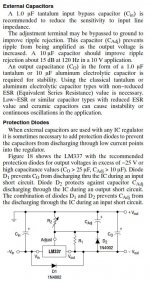
Found this in the datasheet for the LM337.
john-paul and elvee, thanks for your input.
Mark, thanks for your continued work and not just blowing us off on this, no need to pay for parts, you do enough already.
Found this in the datasheet for the LM337.
john-paul and elvee, thanks for your input.
Mark, thanks for your continued work and not just blowing us off on this, no need to pay for parts, you do enough already.
Attachments
Last edited:
I was curious as to how close the 22n was to oscillation, so I soldered tacked in a few other values to see. 10,12,14,16,18, all still had issues though not as bad. It looks like 20n if finally becomes stable, but I did see a strange swing as I increased voltage as it it dropped once .5v and then went back up. I put the 22n in and it is stable, but I think that a bit to close, so I am going to go ahead go with a 33n and make the change to R14 as well. I'd rather have a larger safety margin than 2n.
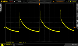
A pic of the waveform and also the schematic with the yellow being where the AC is and the red OK designating that there is no AC. The IN of regulator is also clean.
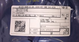
They didn't have the 863-LM337TG regulator, so I used LM337KCSE3
I am starting to think: that might be significant. All of the VRDN boards I have built and tested, used LM317s pulled from the bag shown below. None of those boards oscillated, not even with the unmodified (6.8nF SERIES 15R) compensation network. I just tested the one I still have, and it doesn't oscillate with (6.8nF SERIES 15R). Not when load current = zero , also not when load current = 50 milliamps.
Although LM337KSCE3 is out of stock at Mouser, I found some at DigiKey and ordered them immediately. I also ordered some of the KSCE3 positive regulators, at the same time. When they arrive I'll build another VRDN and see whether I can get it to oscillate.
It might be enough to scare you away from simulation completely, since you have no idea whether the simulation macromodel you've got in hand, is for the manufacturer's chip that you bought, or for the one you didn't buy.
_
Attachments
Let's see what your results are, if you still can't verify, I can ship you mine, as I already have TGs on the way because I was convinced this was the issue. I know I didn't screw up or change anything, but that part, so I'm going with Occam.
The P never had an issue and functions flawless. FYI
Let me know what you find....
JT
The P never had an issue and functions flawless. FYI
Let me know what you find....
JT
Last edited:
Hi,
Will the LM337BTG work as a suitable replacement for the 863-LM337TG?
https://www.mouser.com/ProductDetail/ON-Semiconductor/LM337BTG?qs=2OtswVQKCOGoOfwNKxF%2F1w%3D%3D
Datasheet of the "BTG" https://www.mouser.com/datasheet/2/308/LM337_D-1773565.pdf
seems to be identical to the "TG". The only difference I can see is the Operating Temp Range (-40 to 125 deg. C for the BTG, and 0 to +125 deg. C for the TG).
The BTG is available (1,271 pieces last time I checked) in Mouser.
Thank you!
Abe
Read the original documentation. It’s 20Vmax if you want to use the denoizer. You could of course omit that Section and just as a very nice PCB that holds 317/337.
Yes, sorry for my poorly phrased question -my bad. I understand I'll need need to omit the De-Noiser and probably uprate the filter caps - just wanted to make sure I hadn't missed something.
Following up on the observation made in post #188, I stuffed and soldered two more VRDN boards. Both of them used the exact same components, pulled from the same Mouser bags, that are called for in the VRDN Detailed Parts List.
EXCEPT: board #2 used TI (not ON Semiconductor) voltage regulator ICs.
Board #2 used the TI LM317KCSE3 (positive voltage regulator) chip, and the TI LM337KCSE3 (negative voltage regulator) chip.
Otherwise the two boards were identical.
Board #1, with ON Semiconductor chips, did not oscillate when Vout= +20V (positive regulator), and it also did not oscillate when VOUT= -20V (negative regulator).
Board #2, with TI chips, did not oscillate when Vout= +20V (positive regulator) however it DID oscillate when VOUT= -20V (negative regulator).
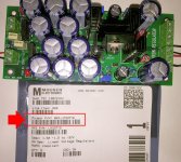
The oscillation I saw (probe on the ADJ pin of the LM337 negative regulator chip) is shown in Figure 1 below. It resembles the oscillation that other members reported. The exact chip used is shown in Figure 2 below.
I will do some investigation, comparing the two boards, hoping to learn why this happens and how to make it stop happening. Meanwhile, I strongly suggest that builders ONLY buy and use the ON Semiconductor LM317 and LM337 part numbers, listed in the Detailed Parts List. Every board I've tested with ON Semi parts, did not oscillate. Similarly, every board I've tested with TI parts (admittedly only one!!) DID oscillate. The prudent thing to do is embrace ON Semi LM337/317 for VRDN, and avoid TI LM337/317 for VRDN, at least until more is known.
_
EXCEPT: board #2 used TI (not ON Semiconductor) voltage regulator ICs.
Board #2 used the TI LM317KCSE3 (positive voltage regulator) chip, and the TI LM337KCSE3 (negative voltage regulator) chip.
Otherwise the two boards were identical.
Board #1, with ON Semiconductor chips, did not oscillate when Vout= +20V (positive regulator), and it also did not oscillate when VOUT= -20V (negative regulator).
Board #2, with TI chips, did not oscillate when Vout= +20V (positive regulator) however it DID oscillate when VOUT= -20V (negative regulator).
The oscillation I saw (probe on the ADJ pin of the LM337 negative regulator chip) is shown in Figure 1 below. It resembles the oscillation that other members reported. The exact chip used is shown in Figure 2 below.
I will do some investigation, comparing the two boards, hoping to learn why this happens and how to make it stop happening. Meanwhile, I strongly suggest that builders ONLY buy and use the ON Semiconductor LM317 and LM337 part numbers, listed in the Detailed Parts List. Every board I've tested with ON Semi parts, did not oscillate. Similarly, every board I've tested with TI parts (admittedly only one!!) DID oscillate. The prudent thing to do is embrace ON Semi LM337/317 for VRDN, and avoid TI LM337/317 for VRDN, at least until more is known.
_
Attachments
Last edited:
Thanks for the update Mark... you can essentially say that 5 boards have the same issue with the TI chip. I built too and so did the other member. That's 5 where the POS did not oscillate on the POS side and did on the Ned side.
Thanks for the update Mark... you can essentially say that 5 boards have the same issue with the TI chip. I built too and so did the other member. That's 5 where the POS did not oscillate on the POS side and did on the Ned side.
Makes me wonder how close the ON is to going into oscillation as well... could always reduce the value of C18 and or increasing the R15 and see if it induces the same oscillation.
I knew it was the TI, but had no direct data... now we do.
JT
Last edited:
VRDN revision A.2: a few component values change, PCB layout doesn't change
I've been doing a lot of experiments with the two almost-identical VRDN PCBs, one has ON Semiconductor voltage regulator ICs (LM317, LM337), and the other has Texas Instruments ICs. As noted above, one of the boards oscillated and the other did not, when the trimpots were set for maximum output voltage.
I've received advice and suggestions from member Elvee, who created the De-Noiser, and also from quite a few other diyAudio members, and I'm very thankful for their advice. I tried what people recommended, I tried the opposite of what people recommended, I tried Latin-Square Design Of Experiments protocols, and in fact I even tried mass quantities of circuit simulation runs. Plus ordinary trial and error of course.
Eventually I settled upon the values shown below. Only component VALUES are changing; the circuit topology remains the same and the PCB layout remains the same. A few resistor values change, and a few capacitor values change. I'll work with diyAudio Moderators to update the Schematic and the Detailed Parts List in Post #1 of this thread. The Gerber CAD files do not change and all PCBs made with those Gerber CAD files, can use this update.
I'm calling it "Revision A.2" because the Rev A PCB Gerbers are still good and so are the boards made from those Gerbers.
"ZEROHM" is a jumper wire, a zero ohm resistor. Automatic PCB assembly shops prefer zero-ohm resistors because those can be handled by the same tape-and-reel equipment as all other resistors. Hobbyists building boards manually, can use plain wire jumpers if desired.
Please keep in mind: the purpose of this change is to prevent VRDN from oscillating when the builder uses TI voltage regulator chips . . . . and to allow builders to use regulator chips from either TI or ON Semiconductor. If you've already built a couple of VRDNs using the Rev.A parts list and using ON Semiconductor chips, you don't need to change anything. However if you used the Rev.A parts list and TI voltage regulator chips, you need to make these changes: your board almost certainly will oscillate.
This is the first time I've personally encountered a circuit where vendor-1's implementation of StandardChipXYZ worked well, while vendor-2's implementation of StandardChipXYZ failed badly. It's a surprise and an embarrassment: the De-Noiser is a relatively simple concept, yet it contains hidden pitfalls. I'm cautiously optimistic that this revision sidesteps the oscillation pitfall.
I've been doing a lot of experiments with the two almost-identical VRDN PCBs, one has ON Semiconductor voltage regulator ICs (LM317, LM337), and the other has Texas Instruments ICs. As noted above, one of the boards oscillated and the other did not, when the trimpots were set for maximum output voltage.
I've received advice and suggestions from member Elvee, who created the De-Noiser, and also from quite a few other diyAudio members, and I'm very thankful for their advice. I tried what people recommended, I tried the opposite of what people recommended, I tried Latin-Square Design Of Experiments protocols, and in fact I even tried mass quantities of circuit simulation runs. Plus ordinary trial and error of course.
Eventually I settled upon the values shown below. Only component VALUES are changing; the circuit topology remains the same and the PCB layout remains the same. A few resistor values change, and a few capacitor values change. I'll work with diyAudio Moderators to update the Schematic and the Detailed Parts List in Post #1 of this thread. The Gerber CAD files do not change and all PCBs made with those Gerber CAD files, can use this update.
I'm calling it "Revision A.2" because the Rev A PCB Gerbers are still good and so are the boards made from those Gerbers.
Code:
ID     Rev.A     Rev.A2
------------------------
R13    15R       ZEROHM
C15    6.8N      10N
R21    0R47      0R33

R14    15R       ZEROHM
C16    6.8N      22N
R22 0R47 ZEROHMPlease keep in mind: the purpose of this change is to prevent VRDN from oscillating when the builder uses TI voltage regulator chips . . . . and to allow builders to use regulator chips from either TI or ON Semiconductor. If you've already built a couple of VRDNs using the Rev.A parts list and using ON Semiconductor chips, you don't need to change anything. However if you used the Rev.A parts list and TI voltage regulator chips, you need to make these changes: your board almost certainly will oscillate.
This is the first time I've personally encountered a circuit where vendor-1's implementation of StandardChipXYZ worked well, while vendor-2's implementation of StandardChipXYZ failed badly. It's a surprise and an embarrassment: the De-Noiser is a relatively simple concept, yet it contains hidden pitfalls. I'm cautiously optimistic that this revision sidesteps the oscillation pitfall.
- Home
- Amplifiers
- Power Supplies
- VRDN: bipolar regulator PCB for line level ckts: ±11V to ±20V @ 1.5A with "De-Noiser"