JT you'll want to find out whether the denoiser is injecting any AC waveform(s) onto the LM337's adjustment pin. In a correctly working regulator, there should be no AC waveform at all ... but your regulator might not be working correctly.
If you bent the leads of resistor R12 following the PCB silkscreen drawing, and then stuffed R12 as the silkscreen shows, then the long loopy end of the resistor (the top end, farthest from the PCB) will be connected to the LM337's adjustment pin. That provides a very convenient place to clip the tip of your scope probe, to display the waveform.
While you have the probe there, snap a picture of the waveshape when (A) the denoiser jumper is removed; (B) the denoiser jumper is added.
_
Attachments

Is this a correct summary:
However,
Do you see why this is suspicious? The only interaction between jumper J4 and the RED PROBE HERE NODE, is through a capacitor: C14 . How is it possible that J4 affects the DC value of RED PROBE HERE NODE ?
1. When you attach your DVM probes to "RED PROBE HERE NODE" and ground,
2. And jumper J4 is not installed,
3. The DVM reads 14.45 volts
2. And jumper J4 is not installed,
3. The DVM reads 14.45 volts
However,
4. When you attach your DVM probes to "RED PROBE HERE NODE" and ground,
5. And jumper J4 is installed,
6. The DVM reads 18.75 volts
5. And jumper J4 is installed,
6. The DVM reads 18.75 volts
Do you see why this is suspicious? The only interaction between jumper J4 and the RED PROBE HERE NODE, is through a capacitor: C14 . How is it possible that J4 affects the DC value of RED PROBE HERE NODE ?
I'm seeing similar strange behavior on the negative channel as well. With the denoiser bypassed I measure about 0.4 mV of AC ripple. If I enable the denoiser the ripple jumps to more than 6 mV and the output voltage no longer is adjustable to the max -20 but to only about -16.
I too built up 2 pcb at the same time and I see the same on both.
I wonder if the Q2 is a problem. I used this part https://www.mouser.com/ProductDetai...PpjosDxSP5Q==&countrycode=AU¤cycode=AUD
I haven't scoped around yet, and I will, but thought I'd mention the similarities.
I too built up 2 pcb at the same time and I see the same on both.
I wonder if the Q2 is a problem. I used this part https://www.mouser.com/ProductDetai...PpjosDxSP5Q==&countrycode=AU¤cycode=AUD
I haven't scoped around yet, and I will, but thought I'd mention the similarities.
Since we both have one side working, we can just start checking voltages from the output back until we find something... not that I will know what to do about it, but it's looking less like a stuff error and probably a parts issue.
We should probably post a subbed arts list.
JT
We should probably post a subbed arts list.
JT
I'm surprised, I didn't see this on any of the boards I built and tested. Unfortunately, I gave them all away, so I can't run a quick re-test this morning. I've got a couple blank boards and most of the parts to quickly build-up another board for testing. I'll be using the exact Mouser part-numbers provided in the Detailed Parts List, with no substitutions or hey-this-is-what-I-happen-to-have-lying-around.
I assume both of you (@ZUM911 and @thompsontechs) have configured your board for a dual secondary transformer?
Please think very carefully about this: connecting a capacitor to ground (via jumper J4), appears to make the DC output voltage change. A capacitor. Makes the DC voltage change. What could that possibly mean? Please think about it.
@ Mark, Yes Dual for me and I understand where you are going with the cap to ground...
I could just save you the build time and expense and ship you one of mine if you like? Meanwhile, I can work on the other and also have other projects. I reviewed the parts list and everything was ordered via the BOM.
EDIT: Found some nasty strange AC switching diode like waveform (guess) Let me prob a bit more gather some data and get back with you before you get to building or I ship to you.
J
Last edited:
@6 I get an initial small reading and it goes back to zero.
@ALL
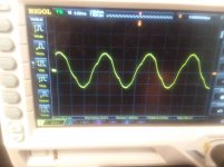
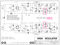
I got the data... and am attaching pics. You can see the Vpp is just under 2v.
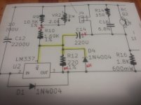
A pic of the waveform and also the schematic with the yellow being where the AC is and the red OK designating that there is no AC. The IN of regulator is also clean.
They didn't have the 863-LM337TG regulator, so I used LM337KCSE3
@ALL
I got the data... and am attaching pics. You can see the Vpp is just under 2v.
A pic of the waveform and also the schematic with the yellow being where the AC is and the red OK designating that there is no AC. The IN of regulator is also clean.
They didn't have the 863-LM337TG regulator, so I used LM337KCSE3
Attachments
Last edited:
Hi Mark, thanks for you help with this.
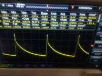
The waveform JT shows is the same shape I see on either side of C14 with the denoiser enabled. I do see a different amplitude of AC on either side though. I see JT has his oscillating at about 241kH, mine oscillates at about 250kH.
Your question about the capacitor to ground. All I can offer is that a capacitor to ground will need a period of time to charge and come to the voltage presented. I suppose if the cap is faulty and has too much ESR it would behave like a resistor. I'm not sure what you mean by "appears to make the DC output voltage change"? I'm assuming you mean the output of the device. It does, in fact, change. It does not appear to change.
As to parts substitutions, I suppose many here would have a stock of some parts, as I do. If I had parts on hand that fit, and following you BOM notes, I used them. A couple resistors and C13/14. I had at 50volt rating not 35. The LM337 in the BOM was not available and I did use the same LM337KCSE3 as JT.
Cheers
Rick
If a HF oscillation is present, it will shift the DC operating point of the regulator, this is not abnormal in itself, it is a consequence of the instability.
Checking/increasing C16 would be the first troubleshooting step (try 10 or 22nF).
Check that R14 is actually 15ohm. You can try to short it, or modify its value.
C22 could also be problematic if it has an excessive ESR, but that's unlikely for a new cap.
Make sure that R22 is actually 0.47ohm, not 4.7 or 47 ohm for example.
The combination of R22 and the ESR of the cap could be excessive, even if R22 has the correct value. You can try to short it, or parallel it with another 0.47 resistor
@Elvee
The POS side works fine, the only dif parts are U2 and Q2 compliment. I have the "official" regulator on the way, so I will try that first, if it still has an issue I will look into your thoughts on values. The resistor values are all okay.
I do thank you for your thoughts.
Mark/6L have thoughts?
JT
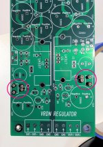
Because I had given away every one of the complete VRDN boards I had built, I didn't have one to run tests upon. So, yesterday afternoon and this morning, I built a new one. Figure 1 shows the new board; I added sockets to make it easy to swap out some of the compensation components. These sockets are circled in pink.
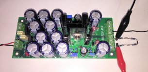
The finished board is shown in Figure 2. I've attached a load resistor which is simply four 100 ohm, 0.5W resistors in series. At 20V output, the current will be (20V / 400R) = 50 milliamps, and the power dissipated in each of the four resistors will be (5V * 50mA) = 250 milliwatts.
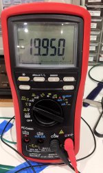
I turned the trimpot VR2 to max clockwise and got -20 volts output, see Figure 3. There was no oscillation visible on the scope, and the output voltage didn't misbehave as I was turning the trimmer potentiometer. There was no instance where turning the pot "up" made the output voltage go "down".
This is the same thing I saw on all the other VRDN boards I've built (and given away). They are all able to output the design max value of 20V, (on both the OUT+ and OUT- halves of the regulator), and none of them oscillate.
The finished board is shown in Figure 2. I've attached a load resistor which is simply four 100 ohm, 0.5W resistors in series. At 20V output, the current will be (20V / 400R) = 50 milliamps, and the power dissipated in each of the four resistors will be (5V * 50mA) = 250 milliwatts.
I turned the trimpot VR2 to max clockwise and got -20 volts output, see Figure 3. There was no oscillation visible on the scope, and the output voltage didn't misbehave as I was turning the trimmer potentiometer. There was no instance where turning the pot "up" made the output voltage go "down".
This is the same thing I saw on all the other VRDN boards I've built (and given away). They are all able to output the design max value of 20V, (on both the OUT+ and OUT- halves of the regulator), and none of them oscillate.
Attachments
Last edited:
So the next thing I did was perform some simulations. I found that the circuit became EVEN MORE STABLE in simulation, if the series RC compensation network was changed. Instead of (6.8 nanofarads SERIES 15 ohms), I found that (33 nanofarads SERIES 1 ohm) was even more stable.
So I removed those components from their sockets and replaced them with 33nF and 1.0R. The VRDN continued to not-oscillate, the output continued to be +20V and -20V. But we have backed up and put even more distance between ourselves and "the cliff of death", therefore we now have greater safety. And that's what I suggest that members @ZUM911 and @thompsontechs try on their boards. For some unknown reason, your stock, unmodified, plain ordinary VRDN boards are less stable than mine. Let's make them MORE STABLE and see whether your issues disappear.
I will be glad to pay your Mouser shipping cost, plus half of the parts cost, to buy the components needed to perform this test. If you pay $4 for parts and $12 for shipping, I'll send you a PayPal for (12 + (4/2)) = $14. We can discuss offline via Private Message.
Mouser part numbers
594-MBB02070C1008FCT
80-R82EC2330DQ50J
_
Attachments
Last edited:
Elvee and Mark, Thanks very much for you help.
I changed C16 to a 22nF COG ceramic cap I have on hand. I changed nothing else. The oscillation is completely gone and I see a very small 55uV AC on the output.
Assuming the ceramic cap is fine to use on the position, I'll sub this part on both side to help my symmetry addiction.
Thanks again fellas.
- Home
- Amplifiers
- Power Supplies
- VRDN: bipolar regulator PCB for line level ckts: ±11V to ±20V @ 1.5A with "De-Noiser"