I have a power supply in a separate metal enclosure for use with low voltage audio equipment. the chassis is earthed via a standard 3 pin connector (earth connection). The idea of the project is for this PSU to connect to separate modules (each in their own metal enclosure) via umbilical cords. The PSU has regulated ±20V + earth output(s) (i.e. '3 wire umbilical).
The '0V' line is to be ground lifted:
Each external module will have it's own internal ± 15V regulator (hence running the main PSU supply to the modules at ± 20V).
BTW I had a spare enclosure, ±18V/160VA toroidal, hefty voltage regulator and some nice power connectors (male and female) lying around so I thought I'd make use of them instead of the expense of separate PSU's for each module.
Also only one 'power button' required on the external PSU to power up all modules and one mains connection.
Many thanks!
The '0V' line is to be ground lifted:
- Should the ground lift be in the main PSU or in each individual module?
- Should the safety ground be connected to each individual module (i.e. a '4 wire connection') from the main PSU?
Each external module will have it's own internal ± 15V regulator (hence running the main PSU supply to the modules at ± 20V).
- One of the modules will be a phono preamp which will require an earth connection to the record player as well.
- The second module is a standard preamp/volume control
- The third will probably be a DAC.
BTW I had a spare enclosure, ±18V/160VA toroidal, hefty voltage regulator and some nice power connectors (male and female) lying around so I thought I'd make use of them instead of the expense of separate PSU's for each module.
Also only one 'power button' required on the external PSU to power up all modules and one mains connection.
Many thanks!
Hi Tony,
I have a 26 preamp with 2 box solution and here is what I did after getting tips here when I posted somewhat similar questions. The preamp is quiet (99dB speakers).
Main PSU (Box 1):
Earth connected to the chassis, at the closest point where it enters the chassis (from IEC socket). No other connection made here and should be secure.
0 Volt from PSU units not connected to the chassis, instead to Box 2 through umbilical (see box 2 description).
Chassis of box 1 connection (I choose a location closest to the output socket of the umbilical exiting chassis 1) to umbilical to chassis of box 2 at the closest to the input of the receiving umbilical socket.
Preamp unit (Box 2):
Incoming 0V (from box 1) to a point (isolated from the chassis) closest to the inputs (RCA). This is the star ground and all other signal ground connects here.
Single (not signal!) wire from here then goes to the switch, then 0.01 uF // with 100 ohms, then to earth of chassis 2. This is the ground lift switch.
I am pretty sure that you will get other responses here and if I describe it wrong, someone will notice it. What I described is what I have.
Hope this helps!
Abe
Last edited:
Hi Abe,
Thanks so much for replying.
So if I've got this right:
The PSU is connected to mains ground and then to 'box 2' chassis via the umbilical.
The 'power lines' from the PSU go to box 2 with the 0V power line connected to an isolated star earth near the RCA jacks from which all box 2 '0V lines' 'radiate'.
A switched connection, via 0.01 uF and 100 ohms in parallel, to box 2 chassis ground to provide ground lift.
Hope that's correct.
BTW, do you use the ground lift switch and do you find it makes a difference to the hum/noise?
That sounds right!
Yes, the ground lift works, in my situation, especially if I use amps with two prong power cords (no earth connection) connected to the preamp. I have not experienced noise with the switch engaged or dis-engaged. Mostly, the ground lift works with hum due to ground loops.
Here's a pic. It shows the "lift" if you trace the white wire from far right right (chassis ground) to the left (switch) with the R//C. From the switch, the white wire goes to the star ground point (0Volt). Notice the larger gauge black wire on the Neutrik connector is the box 1 chassis ground from the PSU.

Abe
Yes, the ground lift works, in my situation, especially if I use amps with two prong power cords (no earth connection) connected to the preamp. I have not experienced noise with the switch engaged or dis-engaged. Mostly, the ground lift works with hum due to ground loops.
Here's a pic. It shows the "lift" if you trace the white wire from far right right (chassis ground) to the left (switch) with the R//C. From the switch, the white wire goes to the star ground point (0Volt). Notice the larger gauge black wire on the Neutrik connector is the box 1 chassis ground from the PSU.
Abe
Last edited:
Maybe take a look at the grounding for the Pearl 2 phono stage.
Building a Pearl 2
Building a Pearl 2
Here's a pic. It shows the "lift" if you trace the white wire...
Abe
Could you re-post the image, please. Your link doesn't work for me. It's probably better to upload images to the diyaudio site rather than use a third party hosting site.
Thanks.
Abe
Could you re-post the image, please. Your link doesn't work for me. It's probably better to upload images to the diyaudio site rather than use a third party hosting site.
Thanks.
Yes, you are right. I wonder why as I never had problems before. Let me try again...
Here you go!
An externally hosted image should be here but it was not working when we last tested it.
Thanks to all for their suggestions.
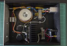
This is my current design. The chassis is reused (why it looks like Swiss cheese in places) and will be sorted out once I have finalised the design.
The ground lift is the elevated brass bussbar just prior to the 3 pin outlet to the bottom left. It comprises 2 back to back diodes with a 10 ohm resistor and 100 nF cap all in parallel (as per Rod Elliot's Project 04) which are connected to the chassis ground at the base and to the 0V line on top (white wire).
The mains input safety earth is also connected to chassis ground under the RF filter fused input socket.
The idea is to use a shielded cable with the 3 pin umbilical with the shield connected to chassis (safety) ground at either end (i.e. PSU and preamp boxes) whilst the 3 wires carry the power. Although I'm not sure this is 100% necessary or particularly a safe way to connect chassis if it is necessary.
Comments appreciated, especially if I've gotten something wrong with the implementation.
Attachments
- Status
- This old topic is closed. If you want to reopen this topic, contact a moderator using the "Report Post" button.
- Home
- Amplifiers
- Power Supplies
- External power supply , safety earth and ground lift