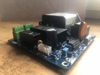
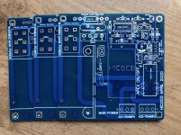
Hi. I am planning a build where I have 2 SMPS (a 350w 48v meanwell and a 60w 5v XPpower). I will be using the 48v for my amp and 5v for raspberry pi and also to power my USB DAC separately (so not powered through RPI USB port). I have 2 questions.
1. I was planning on having an on-off switch between the mains and the PSUs so that both PSUs and the devices connected to them all get power at once. My IEC connector is fused and has a switch but would prefer one on the front.
For me simpler is better as I am still just learning. I have a (very) old Sharp tuner that I might gut out and use the chassis for my amp. This old tuner has a nice push button of-off switch that is connected straight to the mains (with a fuse in between). The switch has lasted about 50 years so obviously had not been stressed in its application. There is writing on the side which says 250VAC/3A/20A. I am in Australia and we have 240V mains. Unsure whether that means it is rated to 3A or 20A. My do PSU's are like 7.3amp and 8A but unlikely to be using that in my application. Regardless though, I imagine that I would be putting more that 3A through it and most certainly a lot more than the tuner was using. I have also read about the issue on inrush current but am still unclear if this is only an issue if the switch is between the PSU and the amp. Is the safest and simplest thing to do here to have the switch just switch a relay with a 240V coil and say 30A rating. Something like the link below? Would this mean the switch is only going have a small current going through it?
HF105F-4/240A1HSTF | Hongfa Europe GMBH SPNO Non-Latching Relay Flange Mount, 240V ac Coil, 30 A Non-Latching Relay | RS Components
2. I was also planning on having a selector switch to swap between the analog inputs at the back of the chassis and the analog inputs coming intot he amp from the the DAC. I was planning on using a signal relay for this and possible powering the relay off the 12v aux supply off my 3e TPA3255 board. If doing this then it would make sense to me that the selector switch would also be connected to a relay which would switch off the power to the 5v psu powering the RPI and DAC. I am guessing that I would need to separate relays. Would it work to have the selector switch hooked up to 2 relays - one 12v signal relay and one 12v relay rated for 250VAC with 30A rating? Something like
https://au.element14.com/panasonic-...lay-signal-dpdt-30vdc-1a/dp/1200949?st=tq2 12
and
https://au.element14.com/multicomp/mc25154/relay-spst-no-250vac-24vdc-30a/dp/1688657
Together they draw around 100mA according to the datasheets. The 12v output on the 3e board is rated to 200mA so should be ok I guess. If this would work ok, would a SPST be ok with wires going to the coils of the relays connected together? The way I see it is they are both only going to the relays so no mixing of signal/power? Or would it be safer to use a DPDT selector switch.
Thanks,
Mark
You probably want signal well away from power, so separate relays for each is in order.
Ever notice the small spark when you plug in your laptop power supply to AC?
SMPS have inrush current and contain a circuit designed to restrict it. Depending on the design, it can be effective on "plug in once" or "cycle AC on/off indefinitely at random intervals". Typically, the plug in once is cheaper and the SMPS is turned on with a logic level "enable" signal, while it remains connected to AC indefinitely. Do your SMPS have "enable" inputs? Usually connect to ground turns on the unit.
Unsure what the 3A and 20A ratings are for; I'd speculate 3A is for inductive load, 20A for resistive. This is because an inductive load will give the contacts a hard time as the current tries to flow initially, causing an arc and burning them as electrical contact is made mechanically. Resistive load not so much.
Last edited:
Here is a link to the 5v SMPS spec sheet.
http://www.farnell.com/datasheets/2...MI8tbz36Hn6QIV1wRyCh2TIgicEAAYAyAAEgKB-fD_BwE
Mine is the model ECM60UT31.
http://www.farnell.com/datasheets/2...MI8tbz36Hn6QIV1wRyCh2TIgicEAAYAyAAEgKB-fD_BwE
Mine is the model ECM60UT31.
Neither units have the "output enable" feature from what I can see, like an ATX PC power supply does. Looks like you'll be switching the AC on/off to operate your system.
The XPPower one is more nicely specified. Surprised they didnt include the AC current on those turn-on delay waveforms.
I noticed the Meanwell one draws little power in the unloaded state, less than 3/4 watt. Perhaps they expect it to run on AC continuously, with the user left to switch the DC output to the load as part of their own design.
Personally I feel safer with the AC powered off, although in my own amp, I have 24V DC available continuously from a used linear industrial DC supply continuously energized by the AC line - so I should talk.
I'd vote for the switch energizing a 240V coil DPST relay, as you proposed, connecting the AC to both power supplies. So "off" is OFF for the whole system. Go on vacation for two weeks OFF...nothing energized.
Hope this helps,
Last edited:
In case it helps, here is also a link for an On/Off switch using momentary push button (On/Off switch using momentary push button).
The good thing about a relay is it switches fast and reduces arcing.
However it comes wit ha price.
A 13 amp mains switch is simplest but I always turn the switch on/off fast to reduce arcing. You can also put a small X2 cap (100nf) across switch contacts to reduce arcing.
However it comes wit ha price.
A 13 amp mains switch is simplest but I always turn the switch on/off fast to reduce arcing. You can also put a small X2 cap (100nf) across switch contacts to reduce arcing.
- Status
- This old topic is closed. If you want to reopen this topic, contact a moderator using the "Report Post" button.
- Home
- Amplifiers
- Power Supplies
- Do I really need a relay for on-off switch?

