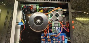
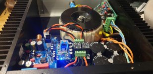
Got it in situ and working nicely. Leds to sort out. Feeding a Dibya Xmas amp. Some initial 'leakage' of the 60hz (50 for me) I read about was illuminating the leds on my crc psu when turned off but after a cycle or two they now don't illuminate when turned off. I understand what is happening .....sort of....so it doesn't bother me. Satisfying clicks from the relays on this board and then the speaker protection board.!
Totally dead silent when turned on and a little mechanical noise from the 5v smps when turned off. Nothing to care about though. Thanks again for the design and guidance
Totally dead silent when turned on and a little mechanical noise from the 5v smps when turned off. Nothing to care about though. Thanks again for the design and guidance
Attachments
Last edited:
Made a little video. Changed one of my cheap but nice Aliexpress latching switches to another one but momentary and one with a 6v rated illumination. Works well. I havent bothered about an 'off' led on the fascia but the one I put on the board is handy for open lid testing i guess. I've ordered some dual colour capacitive switches. We will see how they work although they are 12v rated so might be very dim or I may have to alter the R value on the LED circuit.
Mark Johnson H9KPXG soft start - YouTube
Apologies for back ground noise.....joiners rebuilding my bay window!
Mark Johnson H9KPXG soft start - YouTube
Apologies for back ground noise.....joiners rebuilding my bay window!
Mark,
Thanks for making this available to the community. Assuming success, it allows me to achieve on/off from the front of my amps.
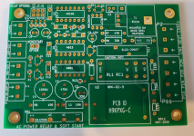
I followed your prod and ordered my boards from JLCPCB and received them within two weeks. Fun process and a bit magical as it works so well.
I'm just about done acquiring all the parts, the SL22-20007 turned into the MS22 20008 as it was the only part I could find. I imagine there is a load of them stuck inside a cargo container just off the CA coast.
Anyway, I have 5 boards I can pass on to other members for $8.00 [part and shipping cost].
Send me a message if you are interested.
Thanks for making this available to the community. Assuming success, it allows me to achieve on/off from the front of my amps.
I followed your prod and ordered my boards from JLCPCB and received them within two weeks. Fun process and a bit magical as it works so well.
I'm just about done acquiring all the parts, the SL22-20007 turned into the MS22 20008 as it was the only part I could find. I imagine there is a load of them stuck inside a cargo container just off the CA coast.
Anyway, I have 5 boards I can pass on to other members for $8.00 [part and shipping cost].
Send me a message if you are interested.
Attachments
Last edited:
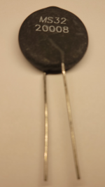
MS32 200008 In-Rush Current Limiter 8A 20 ohm
I finally tracked down the elusive - at least for me - MS32 200008 In-Rush Current Limiter 8A 20 ohm out of the UK.
I have 5 I can ship [US only] if you'd like one. $5.00 [my cost] + $3.00 shipping.
Send my a PM.
I finally tracked down the elusive - at least for me - MS32 200008 In-Rush Current Limiter 8A 20 ohm out of the UK.
I have 5 I can ship [US only] if you'd like one. $5.00 [my cost] + $3.00 shipping.
Send my a PM.
Attachments
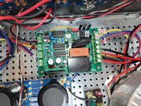
I got my first soft start board soldered-up and tested today, ready to go into my BenMah 'Fokin'...
I had an initial bit of headscratching when I couldn't get the momentary switch to operate but it really helps if you don't omit a component during assembly!
Having installed the poor forgotten resistor all is now well.
I had an initial bit of headscratching when I couldn't get the momentary switch to operate but it really helps if you don't omit a component during assembly!
Having installed the poor forgotten resistor all is now well.
Not quite there yet.
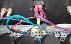
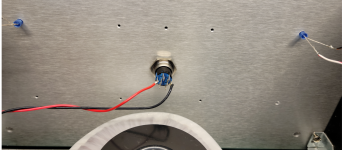
I've installed into my F5. The off LED works, but the on LED does not.
I'm using a MC010920 Vandal Resistant Switch. It lights up before I press it and stays lit after it's in the on position, so I don't have that wired correctly.
I get about 10 VDC per channel from my PSU which normally is 24 VDC.
The board should be constructed correctly, I think my wiring is wrong somewhere. I followed the wiring scheme provided by Mark.
Something needs correction.
Appreciate any help
Attachments
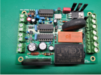
I noticed that something wasn't quite right with my installation so I did some checking and something needs fixing.
I am seeing mains voltage at the outputs as soon as I apply power to the input, regardless of the switch state, so there is clearly something at fault in the Triac section.
The 'logic' part of the board seems well, the on/off LEDs operate correctly and there is a nice relay click.
I have some troubleshooting to do - I'll check the status of the three legs of the Triac in the different switch states first as I assume it must be conducting between pins 1 and 2, either because its faulty or it's permanently switched on by a voltage at pin3.
I have a second board that is complete apart from the little SMPS module (on backorder) but I guess I could hook up a 5V wall wart to use it for comparison.
Last edited:
Chiptech
..I think the 2 outer contacts of your switch are just for the led. You need to use some of the inner ones. Maybe marked NC or NO.
and don't forget you need the jumper installed if the switch is momentary action.
Chiptech
..I think the 2 outer contacts of your switch are just for the led. You need to use some of the inner ones. Maybe marked NC or NO.
I moved them to NO position. Now the switch LED does not work. I am getting a low DCV reading from the PSU.
I don't hear the click from the relay turning on.
I don't understand the wiring to the switch from the CB. Do I run four lines from the switch out on the board to the Switch?
Or is the CB goofed up somewhere? Meaning something I messed up? I'm researching ways to test the board, which is probably what I should have done in the first place.
Thanks
Last edited:
You'll need the 2 outer wires for the led. Feed from the 'LED on' terminal.
Then for the switching itself you should see a terminal on there marked 'C'. Use that for one wire, and one of the NO terminals for the other wire. These two go to the 'switch' terminals on the pcb obviously. If it is a momentary switch you need the jumper on the pcb as Ray mentioned earlier today.
Hope this helps
- Home
- Amplifiers
- Power Supplies
- PCB: low voltage On-Off switch drives AC mains relay \ includes soft start .. H9KPXG