Hi,
I can use this for the switch (I have the latching type) https://www.mouser.com/datasheet/2/140/eswitch_07142017_PVA6-1165859.pdf or do I need a the 120V type?
I saw Mark's Post (#79) for this https://www.mouser.com/Electromechanical/Switches/Pushbutton-Switches/_/N-5g30?P=1yl0rtzZ1yy48toZ1z0z2xkZ1z0z2qg which is a 120V type. I think I ordered the wrong one?
Abe
Got it! Thank you!The little switch only sees low voltage. It controls the relay which sees the mains.
Hidden in plain sight; from post #1 of this thread
...
The actual front panel switch connects at top left; it switches only 5V DC at 0.5 milliamperes. This ripples through some digital logic gates ...
The only documentation is post #1 of this thread. Attached to it, at the bottom of the post, are
Caution: this project is not suitable for beginners. It assumes the builder has already successfully built several PCB-based electronics projects. It assumes the builder has already learned how to (A) read a parts list, and then to (B) choose and buy electronic components, at a first-tier distributor like DigiKey or Element14 or Mouser. It assumes the builder knows how to read a schematic diagram. It assumes the builder owns an inexpensive component tester such as the Mega328 (here is one of MANY sales pages at eBay) and knows how to use it. It assumes the builder has already ordered PCBs from a fab, using Gerber CAD files. And so forth.
Several members of diyAudio have already used these Gerber files to order PCBs for themselves. They ordered components from the parts list, stuffed & soldered the board, cleaned off any excess flux, and found that the final assembly worked beautifully. Have a look through the thread for their posts and for my congratulations upon their success. These folks are living proof that it CAN be done, it HAS been done, and it WILL be done again. Perhaps by you!
However, if you don't quite meet these criteria yet, you can always request other DIYers to build one for you. Discover a mutually agreeable arrangement so that each person is happy with the outcome; a "Win-Win deal". This might involve food, beverages, audio equipment, money, tools, or anything else the two of you can imagine.
_
- Circuit Schematic diagram (attachment #4)
- Detailed parts list (#9)
- Gerber files for PCB manufacturing, in a .zip archive (#10)
- Side by side photos of bare PCB and fully assembled & tested PCB (#8)
- Oscilloscope photos of the circuit in operation (#2, 6, 7)
Several members of diyAudio have already used these Gerber files to order PCBs for themselves. They ordered components from the parts list, stuffed & soldered the board, cleaned off any excess flux, and found that the final assembly worked beautifully. Have a look through the thread for their posts and for my congratulations upon their success. These folks are living proof that it CAN be done, it HAS been done, and it WILL be done again. Perhaps by you!
However, if you don't quite meet these criteria yet, you can always request other DIYers to build one for you. Discover a mutually agreeable arrangement so that each person is happy with the outcome; a "Win-Win deal". This might involve food, beverages, audio equipment, money, tools, or anything else the two of you can imagine.
_
Last edited:
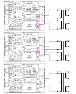
I received a Private Message from a diyAudio member, who asked how to connect a 230V transformer with a single secondary.
Since I think the Forum is by far the best way to share technical expertise across the whole community, I will put my reply here where everyone can see it, and possibly reply with their own thoughts.
The member drew a very beautiful figure which illustrates his/her opinion about the right way to connect three different transformers to H9KPXG. I agree with all of them! I congratulate you on a beautiful piece of engineering communication. I think I would also mention, very briefly, that it is also perfectly fine / perfectly harmless to add a jumper in location "P10" for the 230V / single_secondary case. The bottom drawing in the stack of three drawings.
Well done!
Mark
Attachments
Nice drawing
Wow. wish I could draw like that. For now, I will just stay focused on the "electron management" portion.
Want to take this opportunity to thank Mark for all he does with this board. My first PCB order, my first normally open/normally closed switch wiring project and it all works perfectly. Three installed so far. Should have had more than 5 boards made.
Don
I received a Private Message from a diyAudio member, who asked how to connect a 230V transformer with a single secondary.
Since I think the Forum is by far the best way to share technical expertise across the whole community, I will put my reply here where everyone can see it, and possibly reply with their own thoughts.
The member drew a very beautiful figure which illustrates his/her opinion about the right way to connect three different transformers to H9KPXG. I agree with all of them! I congratulate you on a beautiful piece of engineering communication. I think I would also mention, very briefly, that it is also perfectly fine / perfectly harmless to add a jumper in location "P10" for the 230V / single_secondary case. The bottom drawing in the stack of three drawings.
Well done!
Mark
So what would be the correct or better way to connect TWO 230V transformers with single primary to one board.
1. Jumper 230V both transformers connected to P1D and P2N.
2. Jumpers across 115V and connect one transformer to P1D - P1N and other P2D - P2N.
sorry for repeating myself...
I would choose whichever option is the least confusing to someone else.
I suppose it might be even better to say "the most intuitive" rather than "the least confusing"
- Your kid, that you give the amp to, when she leaves for college
- A repair person
- The next owner after you. Maybe you'll sell the amp, maybe your widow will sell it upon your death, etc.
Hey Mark. Could I ask you how I could adapt this circuit to work on the DC side only? Right now, I'm thinking a depfet like IXTH6N50D2 as a current limiting pass device? The goal is to limit chargine current to ~2A. a 1R resistance in the source leg of the MOSFET would do it?
Last edited:
For DC in, DC out, I imagine the smart play is to discard this H9KPXG schematic completely and start over from scratch. The heart of this circuit is an AC-to-DC converter which I very much doubt you will need. The second most important component in this circuit is a triac, a semiconductor switch which is highly optimized to handle mains AC ... that you don't need to be switched.
I recommend that you and your circuit design consultant get a booth at a pizza restaurant and stay there for 2-3 hours, brainstorming about what you ACTUALLY want, what you ACTUALLY need, what you can ACTUALLY afford, and how these things might possibly be accomplished on two layer boards using thru hole parts only. It will take you guys a while to hash out priorities and tradeoffs. I am super confident to predict that the design you leave with, will have strikingly different features than you THOUGHT you wanted when you arrived at the pizza booth.
On the other hand, what you read here is "free advice" and worth every penny you paid for it.
Q re pcb fabrication
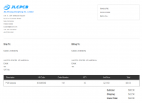
I have heard that OSH Park is a pcb maker that many hobbyists use. I like that it is located in the U.S., although it is a bit more expensive than the Chinese fabricators. I obtained a quote of $57.25 for 3 pieces, which does not seem too bad. However, if I want 2 oz. copper (which I do) they fabricate a thinner board (.8mm thick instead of 1.6mm). Does that disqualify them or is it okay to have the thinner board?
Thanks for any insight anyone can give.
Jazzzman
Hi Mark,
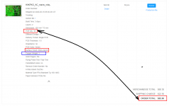
I'm just going through the BoM and realized that the Meanwell IRM-02-5 is not in stock at Mouser or Digikey... I did find those ones though with the same footprint
PSK-S2C-5 from CUI Inc.
RAC02-05SGB from Recom
RAC02-05SGA from Recom (this one is more household)
Would you recommend any of those or should I wait for the Meanwell?
Thanks
Do
- Home
- Amplifiers
- Power Supplies
- PCB: low voltage On-Off switch drives AC mains relay \ includes soft start .. H9KPXG